Hub driving assembly

A hub drive and assembly technology, applied in the direction of hub, motion deposition, power unit, etc., can solve the problems of hub wear, hindering hub rotation, and the inability of the reducer to obtain the reduction ratio, etc., and achieve the effect of large rigidity and large reduction ratio.

Inactive Publication Date: 2016-06-22
SCHAEFFLER TECH AG & CO KG
View PDF5 Cites 11 Cited by
  • Summary
  • Abstract
  • Description
  • Claims
  • Application Information

AI Technical Summary

Problems solved by technology

[0016] The problem to be solved by the present invention is: the rigidity of the wheel hub bearing in the existing wheel hub drive assembly is insufficient; when the hard object on the road surface is stuck into the inner peripheral surface of the wheel hub during the driving of the vehicle, the hard object will hinder the rotation of the wheel hub and cause damage to the wheel hub. Wear; the reducer cannot obtain a large reduction ratio

Method used


Image

  • Hub driving assembly
  • Hub driving assembly

Examples


no. 1 example

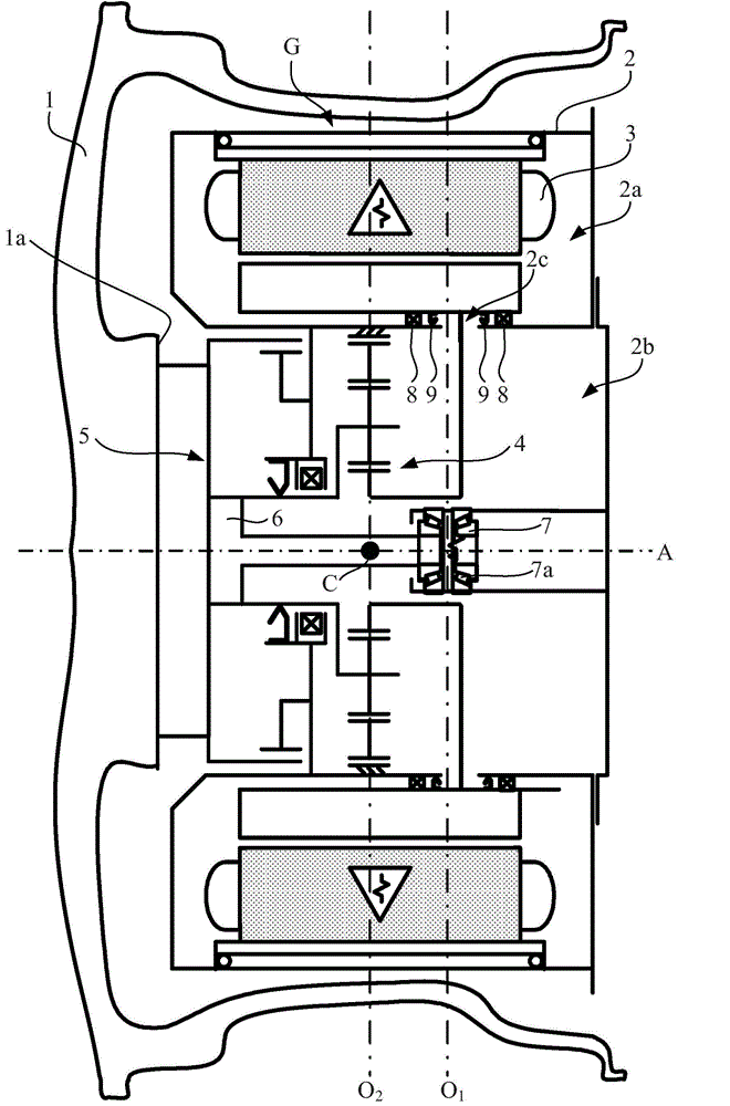
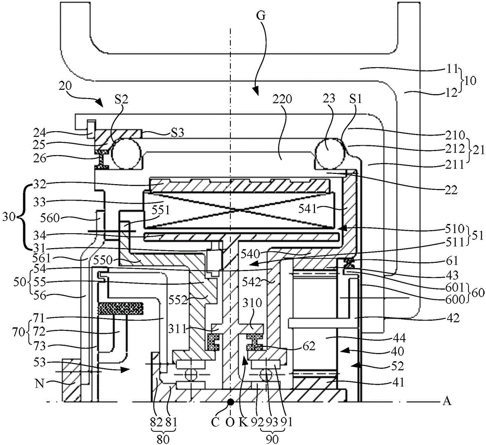
[0041] Such as figure 2 As shown, the hub drive assembly of this embodiment includes: a hub 10 , a hub bearing 20 located in the hub 10 , a motor 30 , a reducer 40 , and a housing 50 . Among them, the wheel hub 10 is used to accommodate the components other than the wheel hub 10 in the wheel hub drive assembly; the wheel hub bearing 20 is used to carry the load transmitted from the vehicle body to the wheel; the motor 30 is used to generate the driving torque that drives the wheel hub 10 to rotate; the speed reducer 40 Used to amplify the driving torque output by the motor 30 . The casing 50 is used to enclose a motor cavity 51 for accommodating the motor 30 and a reducer cavity 52 for accommodating the reducer 40 .

[0042] The motor 30, the speed reducer 40, and the casing 50 are all located on the radially inner side of the hub bearing 20, that is, the hub bearing 20 surrounds the motor 30, the speed reducer 40, and the casing 50, and plays a role in accommodating all par...

no. 2 example

[0103] The difference between the second embodiment and the first embodiment is that in the second embodiment, the wheel hub bearing is not provided with a special outer ring, but is used as the wheel hub, which simplifies the structure of the wheel hub drive assembly. In the second embodiment, the rolling elements in the hub bearing may directly contact the inner peripheral surface of the hub.

[0104] In the second embodiment, since the hub doubles as the outer ring of the hub bearing, when the vehicle is running, hard objects on the road will not enter the radial inner side of the hub, so no hard objects will be stuck into the inner peripheral surface of the hub , and hinder the rotation of the hub and cause wear and tear on the hub.

[0105] In addition, compared with the first embodiment, the technical solution of the second embodiment also has the following advantages: all the space in the hub can be used to accommodate components other than the hub in the hub drive asse...


PUM


Abstract

A hub driving assembly comprises a hub, a hub bearing, a motor, a speed reducer and a housing, wherein the hub bearing is positioned in the hub. The hub bearing comprises an outer ring, an inner ring and a rolling body, wherein the rolling body is positioned in a radial gap between the outer ring and the inner ring; the housing defines a motor chamber, in which the motor is accommodated, and a speed reducer chamber, in which the speed reducer is accommodated; an output end of the motor extends out of an opening of the motor chamber and is connected with an input end of the speed reducer; an output end of the speed reducer is connected with the hub; the motor, the speed reducer and the housing are all positioned on the internal side of the hub bearing in a radial direction; the outer ring is fixedly connected with the hub, or the hub is also used as the outer ring; and the inner ring is fixedly connected with the housing. According to the technical scheme of the invention, problems that the rigidity of the hub bearing in the traditional hub driving assembly is not enough, hard matters may stop the rotation of the hub and wear and tear the hub when the hard matters on a pavement are clamped into the internal circumferential surface of the hub in the vehicle running process, and the speed reducer cannot obtain a large speed reduction ratio are solved.

Description

technical field [0001] The invention relates to the field of automobiles, in particular to a wheel hub drive assembly. Background technique [0002] An electric vehicle refers to a vehicle that is powered by an on-board power supply and uses a motor to drive the wheels. It includes a hub drive assembly for driving and braking the wheels. The hub drive assembly integrates power, transmission and braking devices into the hub. , thus greatly simplifying the mechanical part of the electric vehicle. [0003] figure 1 It is a simplified schematic diagram of the structure of an existing hub drive assembly, such as figure 1 As shown, the hub drive assembly includes: a hub 1; a housing 2 located inside the hub 1, the housing 2 is always stationary when the vehicle is running, there is a gap G between the housing 2 and the hub 1 in the radial direction, and there is a motor chamber 2a in communication and the reducer cavity 2b, the reducer cavity 2b is located on the radial inner s...

Claims


Application Information

Patent Timeline
Patent Type & Authority Applications(China)
IPC IPC(8): B60B27/00B60B27/04B60K7/00
Inventor 黄超潘杭一
Owner SCHAEFFLER TECH AG & CO KG
Why Eureka
Try Eureka