Conveying and pressing device for ceramic cutting

A technology of ceramics and conveyor belts, applied in the direction of conveyors, transportation and packaging, etc., can solve the problems of limited firmness and limited effect of the drive roller, and insufficient clamping of the clamping and fixing device, so as to achieve firm compression, good effect, Good tension effect

Active Publication Date: 2016-06-22
许仙福
View PDF9 Cites 6 Cited by
  • Summary
  • Abstract
  • Description
  • Claims
  • Application Information

AI Technical Summary

Problems solved by technology

[0002] Existing ceramic products are usually conveyed by conveyor belts. During conveying, the conveyor belt is usually tensioned by two transmission rollers, which is realized by adjusting the distance between the two transmission rollers, so that one of the two transmission rollers must be It can move laterally, so that the firmness of the two transmission rollers is limited, and its effect is limited, and the clamping and fixing device on the existing conveyor belt is not firm enough, and the effect is limited

Method used


Image

  • Conveying and pressing device for ceramic cutting
  • Conveying and pressing device for ceramic cutting
  • Conveying and pressing device for ceramic cutting

Examples


Embodiment

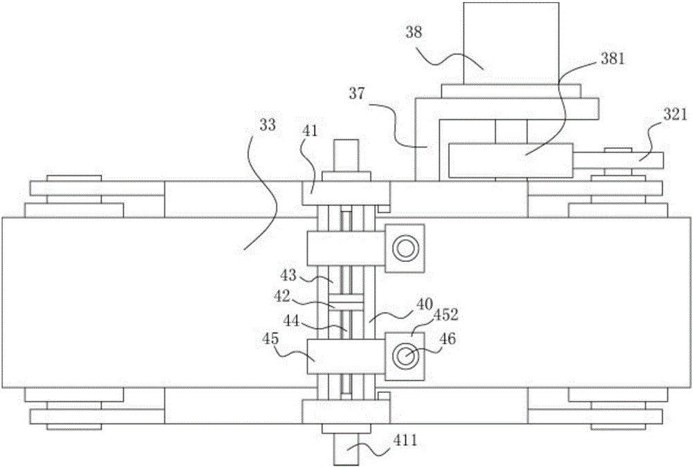
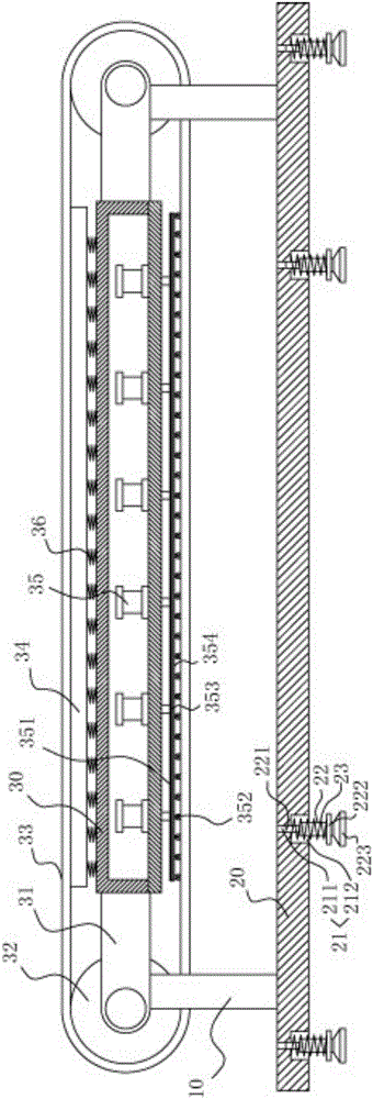
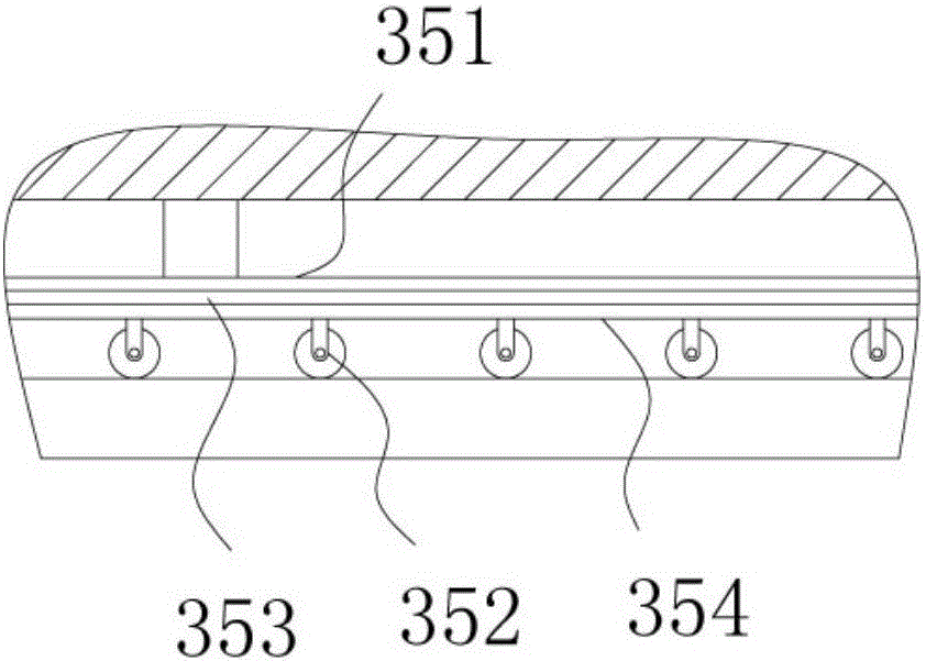
[0021] Example: see Figure 1 to Figure 5 As shown, a ceramic cutting, conveying and pressing device includes a frame 10, and the legs of the frame 10 are fixed on the bottom support plate 20;

[0022] The frame 10 includes a middle housing 30, the front and rear ends of the left and right outer walls of the middle housing 30 are fixed with support plates 31, and the two ends of the transmission roller 32 are hinged on the corresponding two support plates 31, Conveyor belt 33 is tensioned on two transmission rollers 32, and supporting leg is fixed on the bottom surface of support plate body 31; On the first vertical support plate 41, the middle part of the upper connecting beam 40 is fixed with a dividing plate 42, and there are two sliding grooves 43 between the dividing plate 42 and the front and rear ends of the upper connecting beam 40, and the adjusting screw rod 44 is directly below the sliding groove 43. , one end of the adjusting screw 44 is hinged on the partition 42...


PUM


Abstract

The invention discloses a conveying and pressing device for ceramic cutting. The conveying and pressing device comprises a rack. Supporting legs of the rack are fixed to a bottom supporting plate. The rack comprises a middle shell. Supporting plate bodies are fixed to the positions of the front end and the rear end of the left outer side wall and the right outer side wall of the middle shell. The two ends of each transmission roller are hinged to the corresponding two supporting plate bodies. A conveying belt is tensioned on the two transmission rollers. Vertical supporting plates are fixed to the front side and the rear side of the top face of the middle shell. Upper connecting beams are fixed to the two vertical supporting plates. A partition plate is fixed to the middle portions of the upper connecting beams. A sliding groove is formed among the partition plate and the front ends of the upper connecting beams, and a sliding groove is formed among the partition plate and the rear ends of the upper connecting beams. An adjusting screw is located under the sliding grooves. One end of the adjusting screw is hinged to the partition plate, and the other end of the adjusting screw is hinged to the corresponding vertical supporting plate. A pressing block is located above the upper connecting beams. The positions of the two transmission rollers are fixed and the two transmission rollers cannot move relatively, a push air cylinder is used for pushing wheels to achieve tensioning, the tensioning effect of the conveying and pressing device is good, and a pressing air cylinder of the conveying and pressing device conducts pressing firmly.

Description

Technical field: [0001] The invention relates to the technical field of ceramic processing equipment, in particular to a ceramic cutting, conveying and pressing device. Background technique: [0002] Existing ceramic products are usually conveyed by conveyor belts. During conveying, the conveyor belt is usually tensioned by two transmission rollers, which is realized by adjusting the distance between the two transmission rollers, so that one of the two transmission rollers must be It can be moved laterally, so that the firmness of the two drive rollers is limited, and its effect is limited, and the clamping and fixing device on the existing conveyor belt is not firm enough for clamping, and its effect is limited. Invention content: [0003] The purpose of the present invention is to provide a ceramic cutting, conveying and pressing device aimed at the deficiencies of the prior art. It adopts two driving rollers to fix the position and not move relative to each other. The t...

Claims


Application Information

Patent Timeline
Patent Type & Authority Applications(China)
IPC IPC(8): B65G23/44
CPCB65G23/44
Inventor 叶侃
Owner 许仙福
Why Eureka
Try Eureka