Backlight module

A backlight module and light source technology, applied in the field of lighting, can solve the problems of high cost, thick thickness, inability to realize ultra-thin whole machine design, etc. Effect

Inactive Publication Date: 2016-06-22
吴冬梅
View PDF8 Cites 4 Cited by
  • Summary
  • Abstract
  • Description
  • Claims
  • Application Information

AI Technical Summary

Problems solved by technology

Existing side-entry backlight modules generally require a backplane, which is costly and thick, and cannot achieve ultra-thin overall design

Method used


Image

  • Backlight module
  • Backlight module

Examples


Embodiment Construction

[0013] In order to make the above objects, features and advantages of the present invention more comprehensible, the present invention will be further described in detail below in conjunction with the accompanying drawings and specific embodiments.

[0014] Reference herein to "one embodiment" or "an embodiment" refers to a particular feature, structure or characteristic that can be included in at least one implementation of the present invention. "In one embodiment" appearing in different places in this specification does not all refer to the same embodiment, nor is it a separate or selective embodiment that is mutually exclusive with other embodiments.

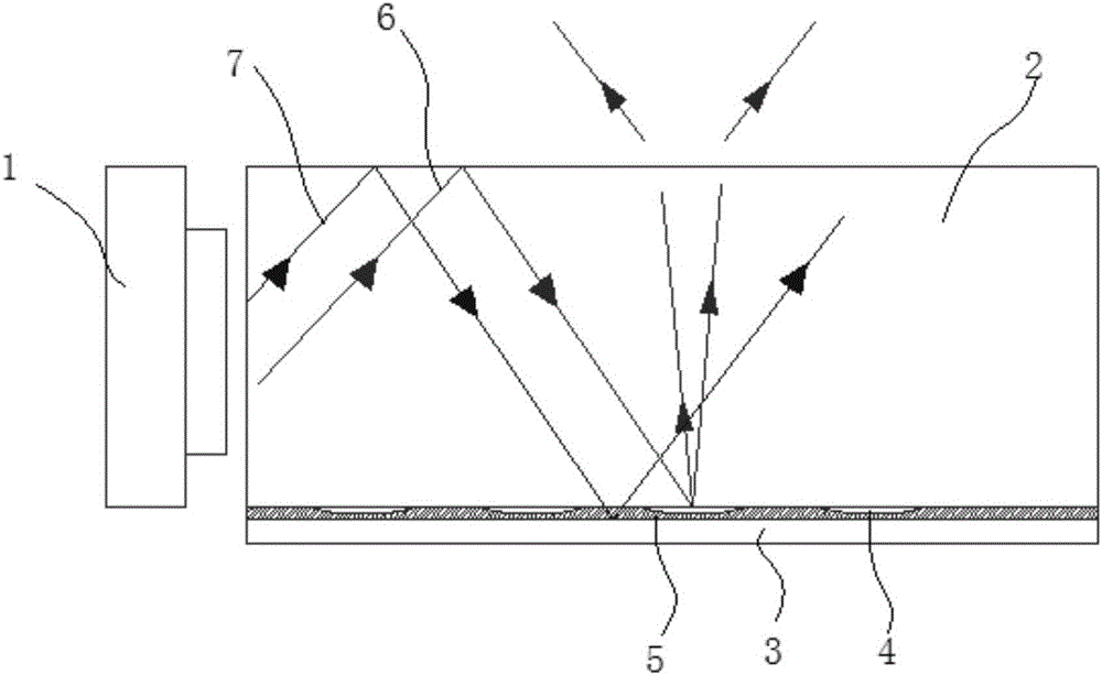
[0015] see figure 2 , which is a structural schematic diagram of a backlight module according to an embodiment of the present invention. see figure 2 . The backlight module of the present invention comprises a light source 1, a light guide plate 2 and a reflection sheet 3, the light source 1 is located on the side of th...


PUM


Abstract

The invention provides a backlight module which comprises a light source, a light guide plate and a reflector plate. The light source is located on the side face of the light guide plate. The bottom face of the light guide plate is provided with a plurality of lattice points arranged at intervals. The reflector plate is attached to the bottom face of the light guide plate and covers the multiple lattice points. The reflector plate is a mirror reflector plate with a mirror reflection function. The backlight module is good in light emitting effect, the thickness of the module can be reduced, and ultrathin complete machine design can be achieved.

Description

technical field [0001] The invention relates to the lighting field, in particular to a backlight module. Background technique [0002] Backlight modules are divided into side-type backlight modules and direct-type backlight modules according to the incident position of the light source. see figure 1 , which is a schematic structural diagram of an edge-lit backlight module in the prior art. The side-type backlight module includes a light source 101, a reflector 102 positioned at the periphery of the light source 101, a reflector 103, a light guide plate 104 located above the reflector 103, a diffuser plate 105 located above the light guide plate 104, and a diffuser plate 105 located above the diffuser plate 105. The prism sheet 106. In the side-lit backlight module, generally, the light guide plate 104 and the reflection sheet 103 are separately assembled in the backplane cavity of the backlight module. Existing backlight modules generally require a backplane or a structu...

Claims


Application Information

Patent Timeline
IPC IPC(8): F21S2/00F21V8/00F21V7/05F21V19/00F21V17/10
CPCF21S2/00F21V7/05F21V17/101F21V19/00F21V2200/00
Inventor 吴冬梅
Owner 吴冬梅
Why Eureka
Try Eureka