Ultra-thin LED indicator lamp saving energy

A technology for LED light strips and indicator lights, which is applied to lampshades, lighting applications, lighting and heating equipment, etc., can solve the problems of thick indicator lights, high energy consumption of indicator lights, and low brightness, so as to reduce the thickness of the overall structure and reduce the The risk of failure, the effect of improving display brightness

Inactive Publication Date: 2014-06-25
CHENGDU KAIYU ELECTRICAL APPLIANCE
View PDF7 Cites 1 Cited by
  • Summary
  • Abstract
  • Description
  • Claims
  • Application Information

AI Technical Summary

Problems solved by technology

[0002] Indicator lights are used in many occasions to indicate the exits, passages and various warnings of buildings such as cinemas and shopping malls. The current indicator lights are composed of lamp holders, lampshades, light-emitting lamps and circuits. They are installed in The luminous lamp behind the lampshade is an ordinary lamp bead with high energy consumption. The entire indicator light is thick and has low brightness;
[0003] When the indicator light is in the daytime or when the light is good, the pattern on the lampshade can be seen directly. At night or in the case of poor light, after the power is turned on, the pre-drawn pattern on the lampshade will appear. On the one hand, the energy consumption is high. At night or when the light is not good, the lights need to be turned on all the time. More importantly, if the power is cut off in an emergency, the indicator lights will not work. Even if a backup power supply is used, frequent maintenance is required. , the lack of complex structure

Method used


Image

  • Ultra-thin LED indicator lamp saving energy
  • Ultra-thin LED indicator lamp saving energy
  • Ultra-thin LED indicator lamp saving energy

Examples


Embodiment 1

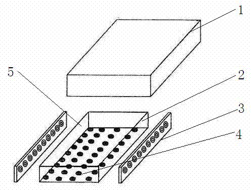
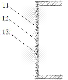
[0019] as attached figure 1 , attached figure 2 , attached image 3 As shown, the LED ultra-thin energy-saving indicator light of this embodiment is composed of a lampshade 1 and an LED light bar 3. A light guide plate 2 is arranged inside the lampshade 1, and an LED light bar 3 is respectively arranged on both sides of the light guide plate 2. The light-emitting surface of the light bar 3 is facing the side of the light guide plate 2, so that the light emitted by the LED lamp can enter the light guide plate 2 from the side, and the bottom surface of the light guide plate 2 is provided with reflective dots 4, which can evenly transmit the light entering from the side of the light guide plate 2 The light is reflected back to the light guide plate 2, so that the light guide plate 2 becomes a surface light source that can emit light evenly, and the top surface of the light guide plate 2 is the light-emitting surface 5; The base layer 11, the self-luminous material coating 12,...


PUM

PropertyMeasurementUnit
Thicknessaaaaaaaaaa

Abstract

The invention relates to an indication sign, in particular to an ultra-thin LED indicator lamp saving energy. The ultra-thin LED indicator lamp saving the energy comprises a lampshade provided with indication patterns in an engraving mode, and LED lamp bars. A light guide board is arranged in the lampshade. The two sides of the light guide board are provided with the LED lamp bars respectively. The light-emitting faces of the LED lamp bars directly face the side face of the light guide board. The bottom face of the light guide board is provided with a light reflection net point. The lampshade is of a three-layer structure formed by overlapping a transparent base layer, a self-luminous material coating and an indication pattern layer, wherein the transparent base layer, the self-luminous material coating and the indication pattern layer are sequentially arranged from inside to outside. According to the ultra-thin LED indicator lamp, as the light guide board is arranged, the light-emitting effect is good, the display brightness of the indicator lamp is improved, the light-emitting brightness of an LED light source is high, and the energy consumption is low; the self-luminous material coating is arranged on the lampshade, even if power is off or the LED lamp is damaged, the indication patterns on the indicator lamp can be displayed for a period of time, and therefore the risk of failure of the indicator lamp under the emergent circumstance can be reduced.

Description

technical field [0001] The invention relates to indicator signs, in particular to an LED ultra-thin energy-saving indicator light. Background technique [0002] Indicator lights are used in many occasions to indicate the exits, passages and various warnings of buildings such as cinemas and shopping malls. The current indicator lights are composed of lamp holders, lampshades, light-emitting lamps and circuits. They are installed in The luminescent lamp behind the lampshade is an ordinary lamp bead with high energy consumption. The entire indicator light is thick and has low brightness; [0003] When the indicator light is in the daytime or when the light is good, the pattern on the lampshade can be seen directly. At night or in the case of poor light, after the power is turned on, the pre-drawn pattern on the lampshade will appear. On the one hand, the energy consumption is high. At night or when the light is not good, the lights need to be turned on all the time. More impor...

Claims


Application Information

Patent Timeline
IPC IPC(8): F21S8/00F21V3/04F21V8/00F21W111/00F21Y101/02
Inventor 何朝菊
Owner CHENGDU KAIYU ELECTRICAL APPLIANCE
Why Eureka
Try Eureka