
Connector wire box fixed on camera bracket

A technology of joint wires and cameras, which is applied in the structural field of power dispatching monitoring auxiliary devices, and can solve problems such as poor waterproof and sunscreen effects, increased construction and maintenance workload, and irregularities.

Inactive Publication Date: 2016-06-22
PENGLAI POWER SUPPLY CO OF STATE GRID SHANDONG ELECTRIC POWER CO
View PDF7 Cites 1 Cited by
  • Summary
  • Abstract
  • Description
  • Claims
  • Application Information

AI Technical Summary

Problems solved by technology

[0002] At present, a large number of infrared integrated cameras are used in electric power video surveillance systems. Among them, the power line and signal line supplying the camera are connected with the camera by winding and connecting with insulating tape to achieve sealing and waterproofing. This connection method mainly has the following defects: 1. , unattractive and irregular; 2. Poor waterproof and sun protection effects, high failure rate; 3. Difficult maintenance, which increases the workload of construction and maintenance

Method used


Image

  • Connector wire box fixed on camera bracket
  • Connector wire box fixed on camera bracket

Examples


Embodiment 1

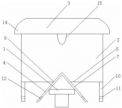
[0018] Example 1: Reference figure 1 . A joint wire box fixed on the top of the camera bracket, comprising a box body 2 installed on the camera bracket 1, the box body 2 is provided with an openable and closable box cover 3, and the bottom surface 5 of the box body 2 is provided with a The body 2 is fixed on the holding device on the camera bracket 1, and the bottom surface 5 both sides of the box body 2 are provided with an auxiliary balancing device used in conjunction with the holding device to improve the stability of the box body 2; the auxiliary balancing device includes a length mounted on the bottom surface 5 The two vertical baffles 10 on the left and right sides of the direction are provided with through holes I11 at the same position of the two vertical baffles 10; the opening 6 runs through the midline length direction of the bottom surface 5, and the holding device runs through the entire length of the opening 6 direction; the holding device includes a left slant...

Embodiment 2

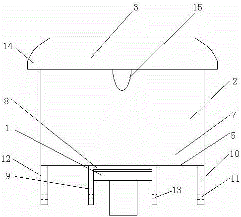
[0021] A kind of connector junction box fixed on the top of the camera bracket of this embodiment, refer to the attached figure 2 , and its difference from Embodiment 1 is that the holding device includes a horizontal plate 8 fixed on the bottom surface 5, vertical connecting plates 9 are installed on the left and right sides of the horizontal plate 8 in the length direction, and the distance between the two vertical connecting plates 9 Matching the width of the camera bracket 1 , through holes III13 are installed at the same positions of the two vertical connecting plates 9 , and the positions of the through holes III13 correspond to the positions of the through holes I11 .

[0022] When in use, you only need to place the box body 2 on the camera bracket 1. If the camera bracket 1 is a plane bracket or a cylindrical bracket, the holding device can be designed as a triangular grip claw shape, with 4 left inclined panels and 7 right inclined panels. It is stuck on the camera b...


PUM


Abstract

The invention relates to a connector wire box fixed on a camera bracket, and belongs to the technical field of a power scheduling and monitoring auxiliary device structure. The box comprises a box body mounted on the camera bracket; an openable and closable box cover is arranged on the box body; a holding device for fixing the box body on the camera bracket is arranged on the bottom surface of the box body; two sides of the bottom surface of the box body are equipped with an auxiliary balancing device; and the auxiliary balancing device matches with the holding device and is used for improving the stability of the box body. The box provided by the invention has the advantages of ingenious structure design, low manufacturing cost, good waterproof and sunproof effect, low fault rate and convenient maintenance.

Description

technical field [0001] The invention relates to a joint box fixed above a camera bracket, and belongs to the technical field of electric power dispatching monitoring auxiliary device structure. Background technique [0002] At present, a large number of infrared integrated cameras are used in electric power video surveillance systems. Among them, the power line and signal line supplied to the camera are connected with the camera by winding and connecting with insulating tape to achieve sealing and waterproofing. This connection method mainly has the following defects: 1. , Unsightly and irregular; 2. Poor waterproof and sun protection effects, high failure rate; 3. Difficult maintenance, which increases the workload of construction and maintenance. Contents of the invention [0003] The purpose of the present invention is to solve the deficiencies in the prior art, and provide a connector box fixed above the camera bracket with ingenious structural design, low manufacturin...

Claims


Application Information

Patent Timeline
IPC IPC(8): H02G3/08H02G3/18
CPCH02G3/081H02G3/088H02G3/18
Inventor 闫大周马世波葛祖郁郭春晓仲惟师刘春江聂晶王朝阳王克欣史春燕杨振东
Owner PENGLAI POWER SUPPLY CO OF STATE GRID SHANDONG ELECTRIC POWER CO
Learn More