Production method for terminal, and terminal

A manufacturing method and terminal technology, which can be used in the manufacture of contacts, parts of connecting devices, and contact parts, etc., can solve the problems of long time and high cost, and achieve the effect of shortening the manufacturing time.

Active Publication Date: 2016-06-22
YAZAKI CORP
View PDF5 Cites 2 Cited by
  • Summary
  • Abstract
  • Description
  • Claims
  • Application Information

AI Technical Summary

Problems solved by technology

[0007] However, the conventional terminal manufacturing method has the problem that since there is a plating process between the stamping process, that is, the punching process, and the bending process, which is also the stamping process, it must be performed between completely different types of processes. Setting and transportation lead to long time and high cost of manufacturing

Method used


Image

  • Production method for terminal, and terminal
  • Production method for terminal, and terminal
  • Production method for terminal, and terminal

Examples


no. 1 approach

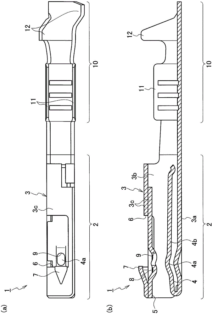
[0023] figure 1 -3 shows the first embodiment. Such as figure 1 As shown, the terminal 1 according to the first embodiment includes a mating terminal connection portion 2 and an electric wire connection portion 10 . The mating terminal connection portion 2 includes: a square cylindrical box portion 3 ; and a spring contact portion 4 arranged in the box portion 3 . The box part 3 includes: a bottom wall 3a; a pair of side walls 3b formed by bending from both sides of the bottom wall 3a; and a top wall 3c formed by bending from upper ends of the side walls 3b on both sides. A terminal insertion opening 5 into which a counterpart terminal (not shown) is inserted is formed on the front surface of the box portion 3 . The top wall 3c is composed of two overlapping panels, and the upper panel is provided with a large notch 6 and a locking lance locking protrusion 7 using the rear surface of the notch 6 as an engaging surface. A terminal contact portion 8 protruding inwardly of th...

no. 2 approach

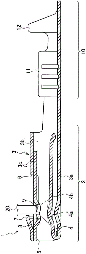
[0039] Figure 4 , 5 The second embodiment is shown. Such as Figure 4 As shown, the terminal 1X according to the second embodiment differs from the terminal 1 according to the first embodiment only in the position and opening size of the plating opening 9X. That is, the opening portion 9X for plating is not provided in the terminal contact portion 8 of the box portion 3 facing the spring contact portion 4, but is provided in a position that does not degrade the function as the terminal 1X (in this case, on the opposite side. The part where the contact resistance increases due to the reduction of the contact area of ​​the terminal). Specifically, the opening portion 9X for plating is provided at a portion of the top wall 3 c obliquely above the groove portion 4 a of the spring contact portion 4 . In addition, the opening size of the plating opening 9X is set larger than the outer diameter size of the nozzle 20X.

[0040] Since the other configurations are the same as thos...

no. 3 approach

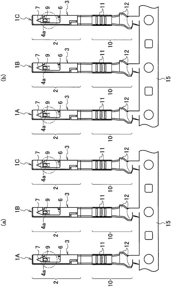
[0046] Image 6 , 7 The third embodiment is shown. Such as Image 6 As shown, compared with the terminals 1 and 1X according to the first and second embodiments, the terminal 1Y according to the third embodiment is not provided with the openings 9 and 9X for plating.

[0047] The same constituent parts as in the first embodiment are denoted by the same reference numerals and description thereof will be omitted.

[0048] The manufacturing process of the terminal 1Y according to the third embodiment is the same as that of the terminals 1 and 1X according to the first and second embodiments, and only the method of spraying gold plating is different. That is, if Figure 7 As shown, in the gold plating spraying, the nozzle 20Y is inserted into the box part 3 from the terminal insertion port 5 of the opposite terminal, and the gold plating solution is sprayed from the entering nozzle 20Y to the spring contact part 4 including the groove part 4a and the spring contact part 4 disp...


PUM


Abstract

This production method for a terminal (1) includes: a first pressing step for pressing a parent material plate made of a conductive metal and punching out a prescribed shape; a second pressing step following the first pressing step, for bending the plate of prescribed shape, and forming a terminal (1) provided with a box part (3) onto the front surface of which opens a terminal insertion port (5) into which a partner terminal is inserted, and a spring contact part (4) arranged inside the box part (3); and a plating step following the second pressing step, for plating at least the spring contact part (4) with a conductive metal.

Description

technical field [0001] The present invention relates to a method of manufacturing a terminal in which a spring contact portion in a case is partially plated, and a terminal manufactured by the method. Background technique [0002] In the terminal having the spring contact portion inside the box portion, since the spring contact portion is surrounded by the firm box portion, reliable and stable spring contact pressure can be ensured with the counterpart terminal. Furthermore, there is an advantage in that, after the spring contact portion is plated with a conductive metal, the electrical resistance of the contact portion with the counterpart terminal can be reduced. [0003] The manufacturing method of the conventional example of this terminal is carried out in the following steps: punching the conductive base material plate into a predetermined shape by punching (punching and punching process); Plating treatment is performed on the parts (plating treatment process); after t...

Claims


Application Information

Patent Timeline
Patent Type & Authority Applications(China)
IPC IPC(8): H01R43/16H01R13/03H01R13/115
CPCH01R4/185H01R43/16H01R4/183H01R13/187H01R43/04
Inventor 宫川大亮
Owner YAZAKI CORP
Why Eureka
Try Eureka