Terminal manufacturing method and terminal
A manufacturing method and terminal technology, which is applied in the manufacture of contacts, components of connection devices, contact parts, etc., can solve the problems of long time and high cost, and achieve the effect of shortening the manufacturing time
- Summary
- Abstract
- Description
- Claims
- Application Information
AI Technical Summary
Problems solved by technology
Method used
Image
Examples
no. 1 approach
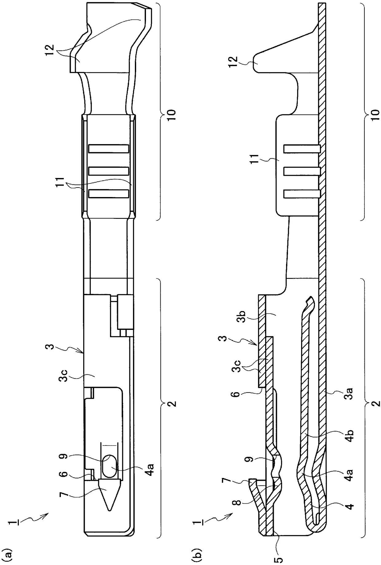
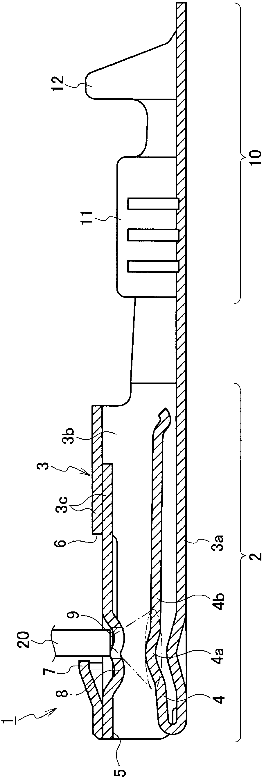
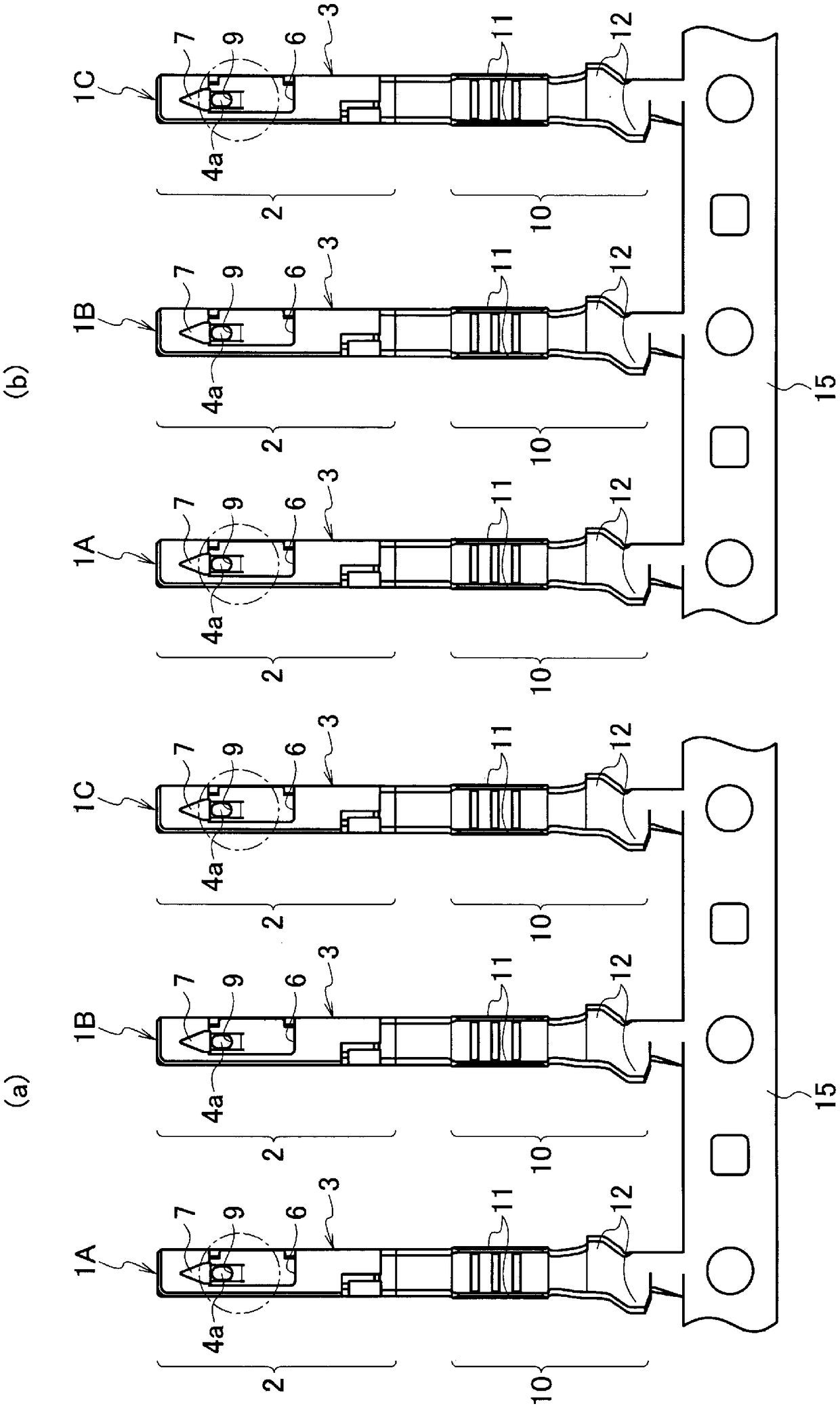
[0023] figure 1 -3 shows the first embodiment. like figure 1 As shown, the terminal 1 according to the first embodiment includes a mating terminal connection portion 2 and an electric wire connection portion 10 . The mating terminal connection portion 2 includes: a square cylindrical box portion 3 ; and a spring contact portion 4 arranged in the box portion 3 . The box part 3 includes: a bottom wall 3a; a pair of side walls 3b formed by bending from both sides of the bottom wall 3a; and a top wall 3c formed by bending from upper ends of the side walls 3b on both sides. A terminal insertion opening 5 into which a counterpart terminal (not shown) is inserted is formed on the front surface of the box portion 3 . The top wall 3c is composed of two overlapping panels, and the upper panel is provided with a large notch 6 and a locking lance locking protrusion 7 using the rear surface of the notch 6 as an engaging surface. A terminal contact portion 8 protruding inwardly of the b...
no. 2 approach
[0039] Figure 4 , 5 The second embodiment is shown. like Figure 4 As shown, the terminal 1X according to the second embodiment differs from the terminal 1 according to the first embodiment only in the position and opening size of the plating opening 9X. That is, the opening portion 9X for plating is not provided in the terminal contact portion 8 of the box portion 3 facing the spring contact portion 4, but is provided in a position that does not degrade the function as the terminal 1X (in this case, on the opposite side. The part where the contact resistance increases due to the reduction of the contact area of the terminal). Specifically, the opening portion 9X for plating is provided at a portion of the top wall 3 c obliquely above the groove portion 4 a of the spring contact portion 4 . In addition, the opening size of the plating opening 9X is set larger than the outer diameter size of the nozzle 20X.
[0040] Since the other configurations are the same as those o...
no. 3 approach
[0046] Image 6 , 7 The third embodiment is shown. like Image 6 As shown, compared with the terminals 1 and 1X according to the first and second embodiments, the terminal 1Y according to the third embodiment is not provided with the openings 9 and 9X for plating.
[0047] The same constituent parts as in the first embodiment are denoted by the same reference numerals and description thereof will be omitted.
[0048] The manufacturing process of the terminal 1Y according to the third embodiment is the same as that of the terminals 1 and 1X according to the first and second embodiments, and only the method of spraying gold plating is different. That is, if Figure 7 As shown, in the gold plating spraying, the nozzle 20Y is inserted into the box part 3 from the terminal insertion port 5 of the opposite terminal, and the gold plating solution is sprayed from the entering nozzle 20Y to the spring contact part 4 including the groove part 4a and the spring contact part 4 dispose...
PUM
 Abstract
Description
Claims
Application Information
 - R&D
- Intellectual Property
- Life Sciences
- Materials
- Tech Scout
- Unparalleled Data Quality
- Higher Quality Content
- 60% Fewer Hallucinations
Browse by: Latest US Patents, China's latest patents, Technical Efficacy Thesaurus, Application Domain, Technology Topic, Popular Technical Reports.
© 2025 PatSnap. All rights reserved.Legal|Privacy policy|Modern Slavery Act Transparency Statement|Sitemap|About US| Contact US: help@patsnap.com


