
Machine frame with variable roller speed ratio

A technology of rollers and racks, which is applied in the field of racks with variable speed ratio of rollers, and can solve the problems that the mill cannot meet the production requirements

Inactive Publication Date: 2016-06-29
JIANGYIN BEIHAI LSA
View PDF0 Cites 0 Cited by
  • Summary
  • Abstract
  • Description
  • Claims
  • Application Information

AI Technical Summary

Problems solved by technology

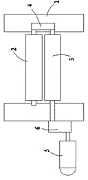
[0002] At present, the open mill used in the field of rubber mixing generally includes a frame, an upper roller that is rotatably arranged on the frame, a lower roller that is rotatably arranged on the frame, and drives the upper roller drum or the driving mechanism for the rotation of the lower roller, the upper roller is located above the lower roller, the speed and speed ratio of the upper roller and the lower roller are fixed, and the above-mentioned open mill exists The following shortcomings: With the development of the market, the products are constantly updated, and the specifications and varieties are diversified. Especially in small and medium-sized enterprises with a wide variety and small quantities, it is difficult to meet the needs of production with a fixed roller speed ratio.

Method used


Image

  • Machine frame with variable roller speed ratio

Examples


Embodiment Construction

[0012] The specific implementation manners of the present invention will be further described below in conjunction with the drawings and examples. The following examples are only used to illustrate the technical solution of the present invention more clearly, but not to limit the protection scope of the present invention.

[0013] Such as figure 1 As shown, a frame with a variable roller speed ratio includes a frame 1, an upper roller 2 rotatably arranged on the frame 1, and a lower roller rotatably arranged on the frame 1 3. A driving mechanism that drives the rotation of the upper roller 2 or the lower roller 3, the upper roller 2 is located above the lower roller 3, the upper roller 2 and the lower roller 3 The above-mentioned lower rollers 3 are connected through a transmission gearbox 4 .

[0014] Such as figure 1 As shown, the upper roller 2 and the lower roller 3 are respectively rotatably connected with the frame 1 through a shaft coupling.

[0015] Such as figure...


PUM


Abstract

The invention discloses a machine frame with variable roller speed ratio; the machine frame comprises a rack, an upper roller rotatingly arranged on the rack, a lower roller rotatingly arranged on the rack, and a driving mechanism for driving the upper roller or the lower roller to rotate; the upper roller is located above the lower roller; the upper roller and the lower roller are connected through a speed change gear box; according to the actual need, through adjusting the speed change gear box, the speed ratio of the upper roller and the lower roller is changed to meet different product needs, and products having different specifications and varieties can be processed.

Description

technical field [0001] The invention relates to a frame with variable speed ratio of rollers. Background technique [0002] At present, the open mill used in the field of rubber mixing generally includes a frame, an upper roller that is rotatably arranged on the frame, a lower roller that is rotatably arranged on the frame, and drives the upper roller roller or the driving mechanism for the rotation of the lower roller, the upper roller is located above the lower roller, the speed and speed ratio of the upper roller and the lower roller are fixed, and the above-mentioned open mill exists The following disadvantages: With the development of the market, the products are constantly updated, and the specifications and varieties are diversified. Especially in small and medium-sized enterprises with a wide variety and small quantities, the open mill with a fixed roller speed ratio is difficult to meet the needs of production. Contents of the invention [0003] The object of the...

Claims


Application Information

Patent Timeline
Patent Type & Authority Applications(China)
IPC IPC(8): B29B7/72B29B7/56
CPCY02P70/10
Inventor 顾中达
Owner JIANGYIN BEIHAI LSA
Learn More