Blank manufacturing process and tooling of a large double-head connecting shaft flange
A manufacturing process and flange technology, which is applied in the blank manufacturing process and tooling field of large double-head coupling flanges, can solve the problems of increasing machining costs, prolonging delivery time, and failing to meet customer delivery time
- Summary
- Abstract
- Description
- Claims
- Application Information
AI Technical Summary
Problems solved by technology
Method used
Image
Examples
Embodiment 1
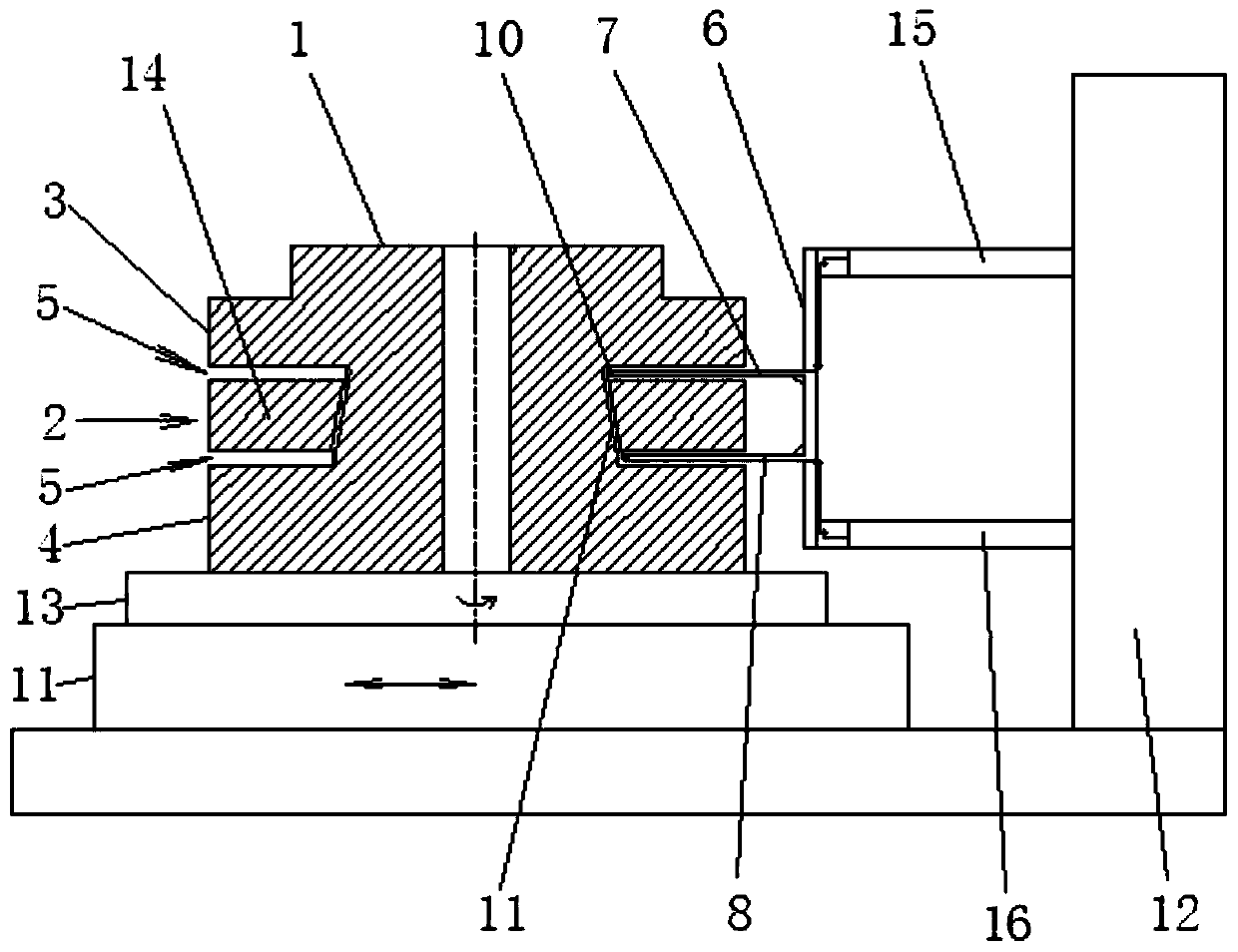
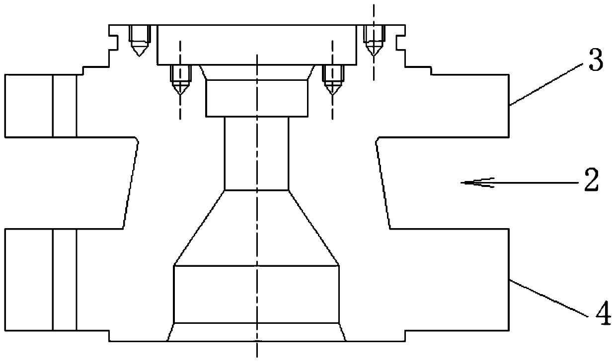
[0043] like Figures 1 to 3 Shown is an embodiment of the blank manufacturing process and tooling of a large double-head coupling flange of the present invention, including flange forging and flange rough machining after flange forging. In the flange forging process, free Forging Forge the double-ended connecting shaft flange 1 into a cylindrical forging blank, and the rough machining process of the flange includes the following process steps:
[0044] (1) Rough machining broaching knife: use a lathe and a turning tool to rough the surface of the cylindrical forging billet;
[0045] (2) Process groove: After rough machining the roughening knife, use groove cutting equipment and cutting tools to place the outer circle 2 of the neck section of the double-head coupling flange 1 close to the back of the upper flange 3 and close to the lower flange 4 A circle of process grooves 5 are respectively processed at the position of the back, and the distances between the process groove 5 a...
Embodiment 2
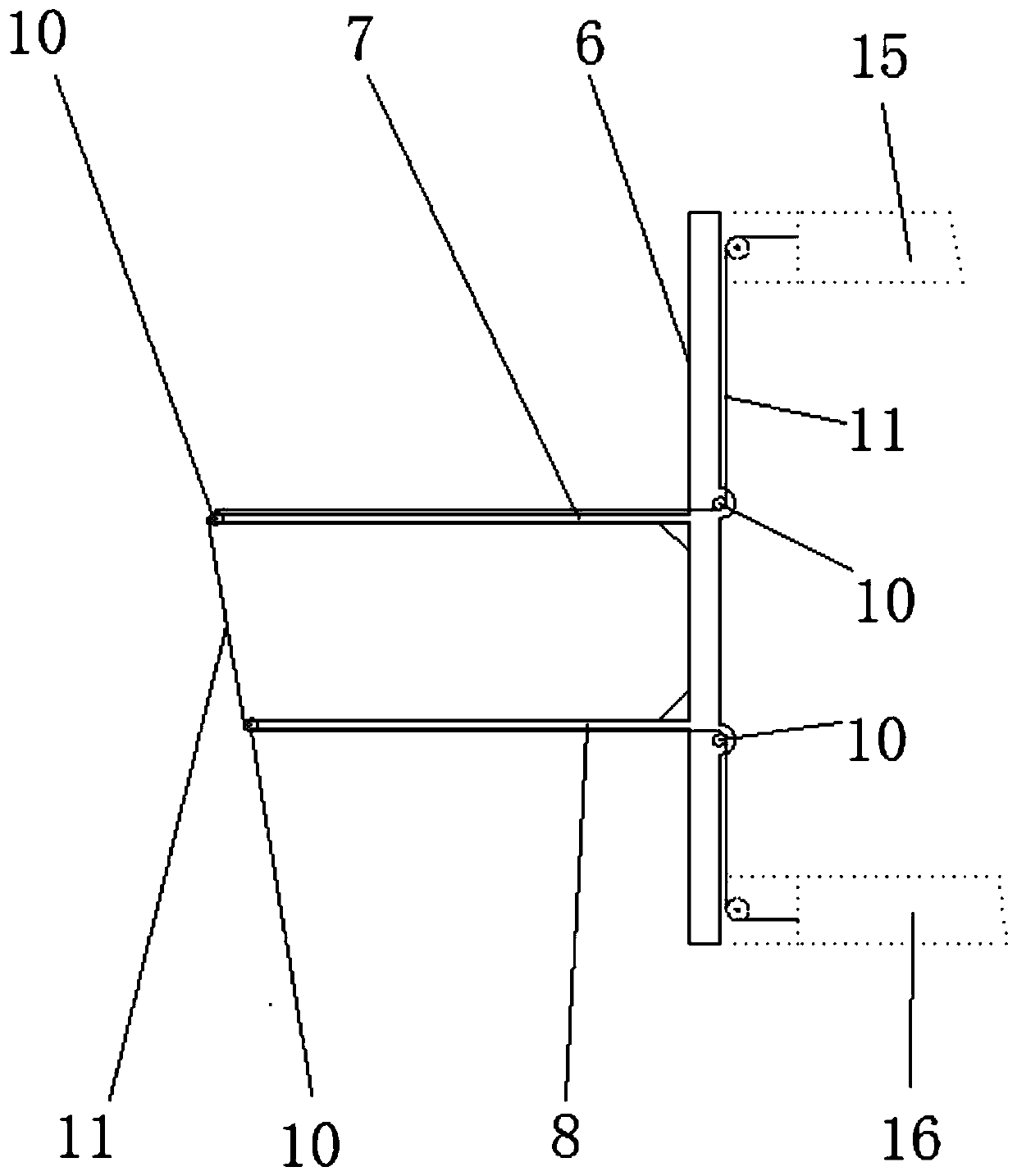
[0063] like Figures 1 to 3 Shown is an embodiment of the tooling used in the blank manufacturing process of the large-scale double-head connecting shaft flange in Example 1, and its specific structure is as follows: the tooling is used for the double-head connecting shaft flange 1 The wire-cutting guide frame 6 for performing wire-cutting processing on the outer circle 2 of the neck section, the wire-cutting guide frame 6 includes an upper guide rod 7 and a lower guide rod 8 arranged horizontally according to the upper and lower positions, and at least on the upper guide rod 7 1. The front end position of the lower guide rod 8 is respectively provided with a guide wheel 10 for positioning and installing wire cutting wire 9, the section height dimension of the upper guide rod 7 and the lower guide rod 8, the outer diameter dimension of the guide wheel 10 All are smaller than the width dimension of the process tank 5 .
[0064] The fixing method of the tooling on the wire cutt...
PUM
 Abstract
Description
Claims
Application Information
 - R&D
- Intellectual Property
- Life Sciences
- Materials
- Tech Scout
- Unparalleled Data Quality
- Higher Quality Content
- 60% Fewer Hallucinations
Browse by: Latest US Patents, China's latest patents, Technical Efficacy Thesaurus, Application Domain, Technology Topic, Popular Technical Reports.
© 2025 PatSnap. All rights reserved.Legal|Privacy policy|Modern Slavery Act Transparency Statement|Sitemap|About US| Contact US: help@patsnap.com


