Large double-head shaft connecting flange blank manufacturing process and tool
A production process and flange technology, which is applied in the blank production process and tooling field of large double-head coupling flanges, can solve the problems of low utilization rate of raw materials, increased machining time, and large blank processing allowance, etc., to increase raw materials The effect of wide utilization, shortening of processing time, and reduction of processing cost
- Summary
- Abstract
- Description
- Claims
- Application Information
AI Technical Summary
Problems solved by technology
Method used
Image
Examples
Embodiment 1
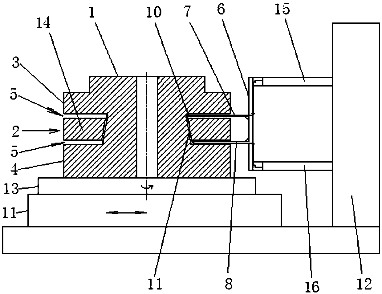
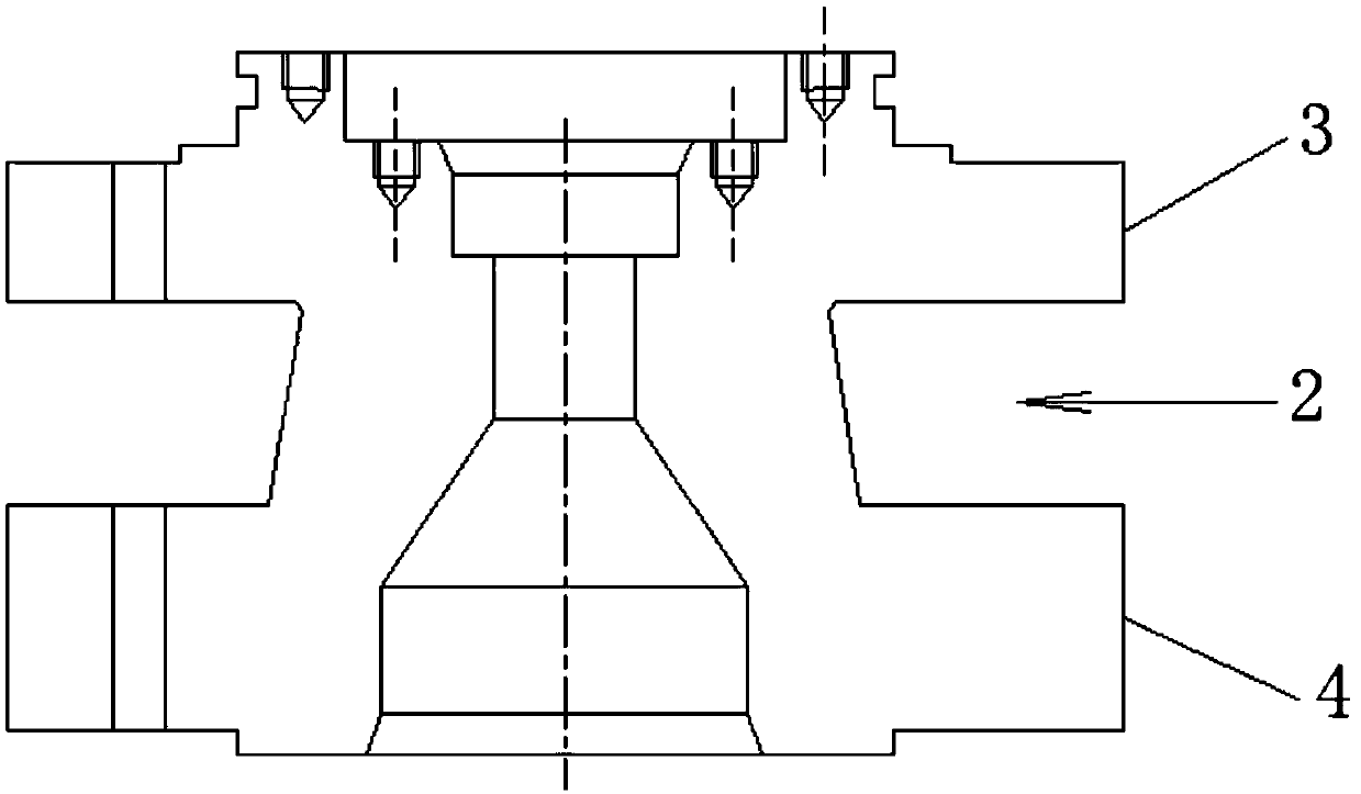
[0043] Such as Figures 1 to 3 Shown is an embodiment of the blank manufacturing process and tooling of a large double-head coupling flange of the present invention, including flange forging and flange rough machining after flange forging. In the flange forging process, free Forging Forge the double-ended connecting shaft flange 1 into a cylindrical forging blank, and the rough machining process of the flange includes the following process steps:
[0044] (1) Rough machining broaching knife: use a lathe and a turning tool to rough the surface of the cylindrical forging billet;
[0045] (2) Process groove: After rough machining the roughing knife, use groove cutting equipment and cutting tools, on the outer circle 2 of the neck section of the double-head coupling flange 1, close to the back of the upper flange 3 and close to the back of the lower flange 4 A circle of process grooves 5 is respectively processed at the position of the back, and the distance between the process gro...
Embodiment 2
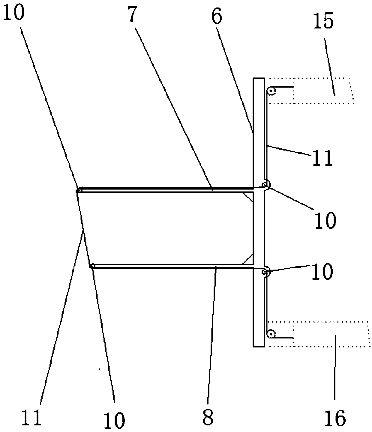
[0063] Such as Figures 1 to 3 Shown is an embodiment of the tooling used in the blank manufacturing process of the large-scale double-head connecting shaft flange in Example 1, and its specific structure is as follows: the tooling is used for the double-head connecting shaft flange 1 The wire-cutting guide frame 6 for performing wire-cutting processing on the outer circle 2 of the neck section, the wire-cutting guide frame 6 includes an upper guide rod 7 and a lower guide rod 8 arranged horizontally according to the upper and lower positions, and at least on the upper guide rod 7 1. The front end position of the lower guide rod 8 is respectively provided with a guide wheel 10 for positioning and installing wire cutting wire 9, the section height dimension of the upper guide rod 7 and the lower guide rod 8, the outer diameter dimension of the guide wheel 10 All are smaller than the width dimension of the process tank 5 .
[0064] The fixing method of the tooling on the wire-c...
PUM
 Abstract
Description
Claims
Application Information
 - R&D
- Intellectual Property
- Life Sciences
- Materials
- Tech Scout
- Unparalleled Data Quality
- Higher Quality Content
- 60% Fewer Hallucinations
Browse by: Latest US Patents, China's latest patents, Technical Efficacy Thesaurus, Application Domain, Technology Topic, Popular Technical Reports.
© 2025 PatSnap. All rights reserved.Legal|Privacy policy|Modern Slavery Act Transparency Statement|Sitemap|About US| Contact US: help@patsnap.com


