A non-linkage transfer mechanism, its transfer method and vamp bonding device

A non-linkage, transfer technology, applied in the direction of transportation and packaging, conveyor objects, etc., to solve the dilemma, improve product quality and production efficiency

Active Publication Date: 2018-10-30
FUZHOU SANJU MECHANICAL & ELECTRICAL EQUIP CO LTD
View PDF4 Cites 0 Cited by
  • Summary
  • Abstract
  • Description
  • Claims
  • Application Information

AI Technical Summary

Problems solved by technology

[0006] Therefore, in order to solve this dilemma, it is necessary to focus on the linkage of the turntable mechanism. Therefore, the purpose of the present invention is to provide a non-linkage system that can ensure both material preparation and transfer, realize no-waiting operation, and improve product quality and production efficiency. transfer mechanism

Method used


Image

  • A non-linkage transfer mechanism, its transfer method and vamp bonding device
  • A non-linkage transfer mechanism, its transfer method and vamp bonding device
  • A non-linkage transfer mechanism, its transfer method and vamp bonding device

Examples


Embodiment 1

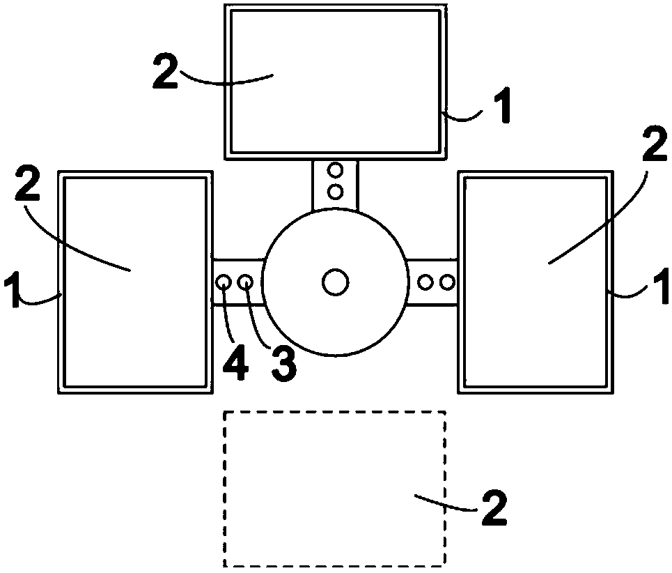
[0047] see Figure 1-Figure 3 As shown, a non-linkage transfer mechanism includes a controller (not shown) and three non-linkage carriers 1, each carrier 1 corresponds to a station 2, which are respectively distributed in different positions in the circumferential direction, and There is a fourth station 2 without carrier. The controller controls each carrier to rotate independently, and can make 1, 2 or 3 carriers shift from their station to another station.

[0048] The carrier 1 can be a template bracket 1 or a transfer platform. Taking template bracket 1 as an example, three template brackets are set, and each template bracket 1 is provided with transfer pin holes 3, such as figure 1 As shown, correspondingly matched with it, there is also a transfer tray 5 driven by a motor and a first positioning mechanism, and the first positioning mechanism will accurately position the template bracket or transfer platform transferred to the station at the station superior. The fir...

Embodiment 2

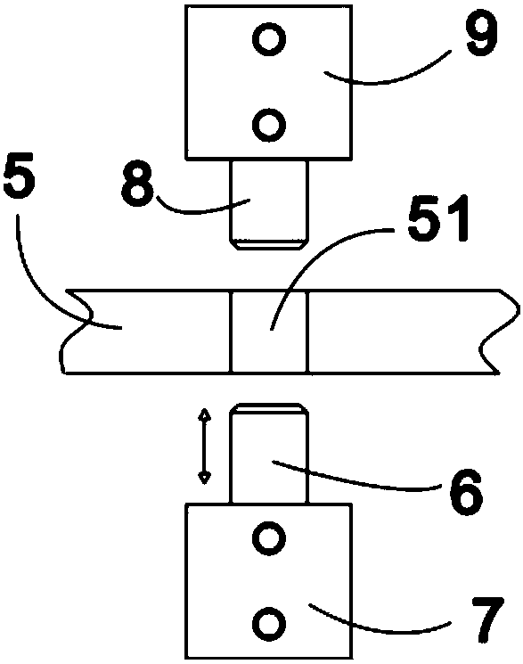
[0062] With reference to embodiment 1, different from embodiment 1, see Figure 4 As shown, the template bracket or the transfer platform is provided with a second positioning mechanism, and the second positioning mechanism is provided with a positioning wheel 13 and a positioning groove 14 correspondingly matched with the positioning wheel 13, and the positioning groove 14 can be attached to the rack. The first positioning mechanism can be automatically released by the positioning pin cylinder, and the second positioning mechanism can be passively released with the rotation of the template bracket or the transfer platform.

[0063] Of course, this embodiment can also be modified as follows: the positioning wheel and the positioning groove are reversed: the positioning groove is arranged on the template bracket or the transfer platform, and the positioning wheel is arranged on the frame.

Embodiment 3

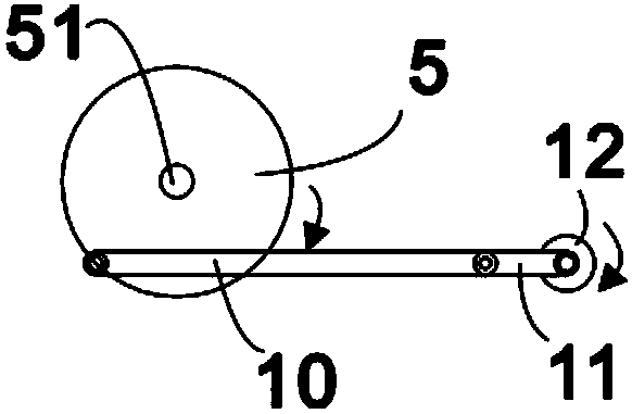
[0065] With reference to embodiment 1, different from embodiment 1, see Figure 5 As shown, each carrier is independently connected to the same circular track 15 , and the controller controls each carrier to independently rotate along the circular track 15 . Both the transfer tray and the template bracket run along the circular track.


PUM


Abstract

The invention provides a non-linked carrier transferring mechanism, a carrier transferring method and a shoe upper laminating device comprising the non-linked carrier transferring mechanism. The carrier transferring mechanism comprises a controller and N non-linked carriers, each carrier corresponds to one station, and the controller controls each carrier to independently rotate and can make M carriers to be transferred to other stations from original stations, wherein N and M are natural numbers, M is smaller than or equal to N, and N is greater than 1. The carrier transferring method comprises the steps that the controller determines the carriers to be transferred, then the carriers to be transferred are subjected to positioning unlocking and movement locking and then are transferred to other stations, and movement unlocking and positioning locking are conducted. The shoe upper laminating device comprises the carrier transferring mechanism, a heating and pressurizing device and a cooling and pressurizing device. It is not needed to prepare materials after hot pressing is finished, neither material preparation nor carrier transferring is neglected, the dilemma problem is solved, and the product quality and production efficiency are improved.

Description

technical field [0001] The invention relates to the field of shoemaking, in particular to a non-linkage transfer mechanism, a transfer method thereof and a vamp bonding device. Background technique [0002] In the field of shoemaking, the non-sewing process of shoes is to fuse the multi-layer upper materials together after melting the hot-melt film, which can save the sewing process, improve the appearance of the product, and increase the production efficiency. Since the adhesive force of the hot-melt film is small in the high-temperature melting state, it is required that the product must be put in immediately after hot-pressing and melting (the sooner the better, otherwise, once the pressure is removed, the material will expand under the action of thermal expansion and contraction) Displacement, wrinkling, degumming, deformation and other phenomena will seriously affect the product quality, and even cause the product to be scrapped) The cold press is cold-pressed and shape...

Claims


Application Information

Patent Timeline
Patent Type & Authority Patents(China)
IPC IPC(8): B65G47/82
CPCB65G47/82
Inventor 余张坚
Owner FUZHOU SANJU MECHANICAL & ELECTRICAL EQUIP CO LTD
Why Eureka
Try Eureka