Lifting hook pulley with function of rapidly regulating rope reeling rate

A hook and rope winding technology, which is applied in the direction of load block, load hanging components, transportation and packaging, etc., can solve the problems of increasing manufacturing cost and maintenance cost, consuming manpower and time costs, etc., and achieves low maintenance cost, assembly and disassembly adjustment Convenient, easy to process, assemble and manufacture

Active Publication Date: 2016-06-29
NANTONG RAINBOW HEAVY MACHINERIES
View PDF5 Cites 6 Cited by
  • Summary
  • Abstract
  • Description
  • Claims
  • Application Information

AI Technical Summary

Problems solved by technology

[0002] In general, considering energy saving and efficiency of large-scale large-tonnage cranes, when the installed power is fixed, two working modes will be set, namely full-load low-speed and half-load high-speed (double the speed of full-load low-speed). According to the past, To achieve two working modes, it can be realized by adjusting the pulley magnification and replacing the hook pulley block or setting up two sets of lifting mechanisms when the crane is designed and manufactured. The former involves rewinding the rope and replacing the hook block every time it is adjusted. Waiting for work requires a lot of manpower and time costs, and the latter needs to increase the manufacturing cost in the early stage and the maintenance cost in the later stage

Method used


Image

  • Lifting hook pulley with function of rapidly regulating rope reeling rate
  • Lifting hook pulley with function of rapidly regulating rope reeling rate
  • Lifting hook pulley with function of rapidly regulating rope reeling rate

Examples


Embodiment Construction

[0020] The present invention will be further described in detail below in conjunction with the accompanying drawings and examples. The following examples are explanations of the present invention and the present invention is not limited to the following examples.

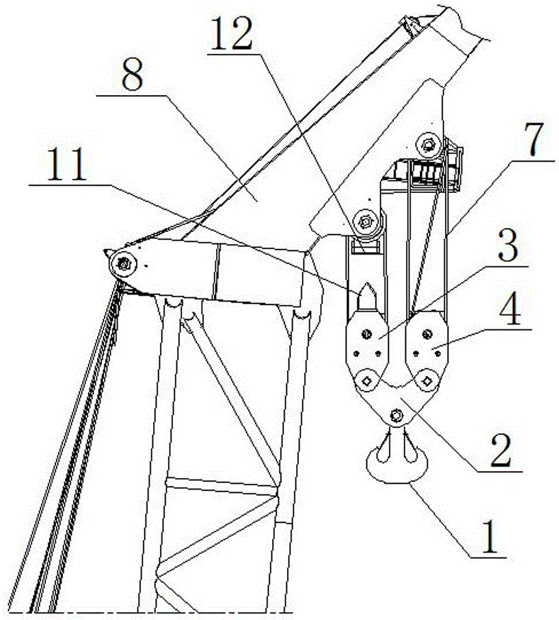
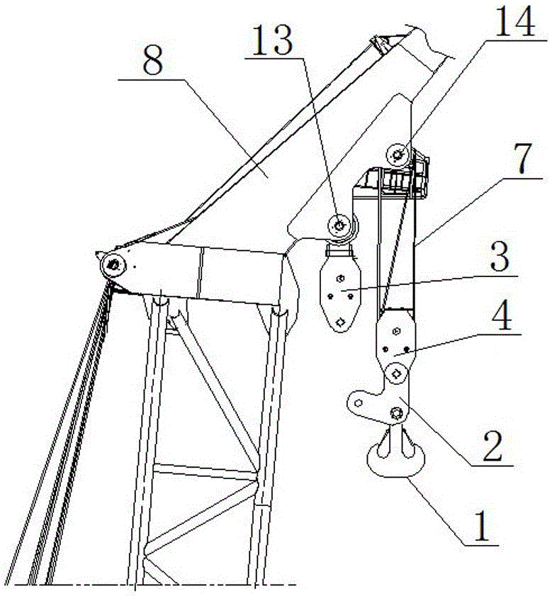
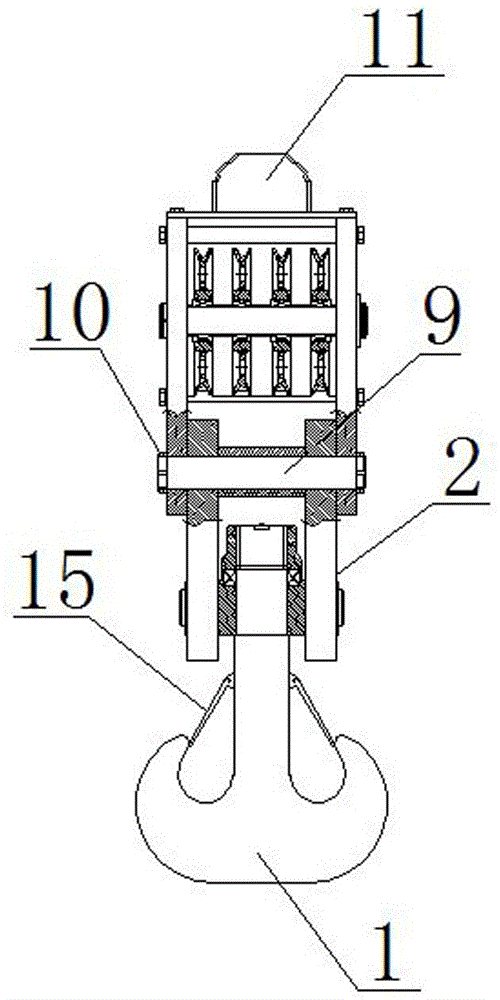
[0021] As shown in the figure, a hook block of the present invention with the function of quickly adjusting the rope winding ratio includes a hook 1, a connecting frame 2, a left pulley block 3, a right pulley block 4, a left hoisting winch 5, and a right hoisting winch 6 and wire rope 7, the hook 1 is hinged at the lower end of the connecting frame 2, one side of the upper end of the connecting frame 2 is hinged at the lower end of the right pulley block 4, the other side of the upper end of the connecting frame 2 is hinged at the lower end of the left pulley block 3 and the connecting frame 2 is hinged with the left pulley block 3 For detachable connection, the left pulley block 3 and the right pulley block 4 are a...


PUM


Abstract

The invention discloses a lifting hook pulley with the function of rapidly regulating the rope reeling rate. The lifting hook pulley is characterized by comprising a lifting hook, a connecting frame, a left pulley block, a right pulley block, a left hoisting winch, a right hoisting winch and a steel wire rope, wherein the lifting hook is hinged to the lower end of the connecting frame; one side of the upper end of the connecting frame is hinged to the lower end of the right pulley block; the other side of the upper end of the connecting frame is hinged to the lower end of the left pulley block; hinging between the connecting frame and the left pulley block is detachable connection; the left pulley block and the right pulley block are arranged at the head of a boom; one end of the steel wire rope is arranged on the left hoisting winch; and the other end of the steel wire rope penetrates through the left pulley block and the right pulley block sequentially and is connected with the right hoisting winch finally. The lifting hook pulley has a simple structure and can rapidly realize the rate regulating function without adding extra overmuch design and manufacturing costs.

Description

technical field [0001] The invention relates to a hook block, in particular to a hook block with the function of quickly adjusting the rope winding ratio. Background technique [0002] In general, considering energy saving and efficiency of large-scale large-tonnage cranes, when the installed power is fixed, two working modes will be set, namely full-load low-speed and half-load high-speed (double the speed of full-load low-speed). According to the past, To achieve two working modes, it can be realized by adjusting the pulley magnification and replacing the hook pulley block or setting up two sets of lifting mechanisms when the crane is designed and manufactured. The former involves rewinding the rope and replacing the hook block every time it is adjusted. Waiting for work requires a lot of manpower and time costs, and the latter needs to increase the manufacturing cost in the early stage and the maintenance cost in the later stage. Contents of the invention [0003] The ...

Claims


Application Information

Patent Timeline
Patent Type & Authority Applications(China)
IPC IPC(8): B66C11/10B66C1/36
CPCB66C1/36B66C11/10
Inventor 关德壮刘荣玉艳军彭光玉
Owner NANTONG RAINBOW HEAVY MACHINERIES
Why Eureka
Try Eureka