
Combined box beam

A combined box and steel box girder technology, applied in bridges, buildings and other directions, can solve the problems of inconvenient fabrication and construction, lack of flanges on the beam, and large demand for steel, and achieves the advantages of increasing compressive stress, simplifying production processes, and increasing efficiency. Effect

Inactive Publication Date: 2016-06-29
BEIJING DISHENG KECHUANG CONSTR ENGCO +1
View PDF0 Cites 1 Cited by
  • Summary
  • Abstract
  • Description
  • Claims
  • Application Information

AI Technical Summary

Problems solved by technology

Nevertheless, the upper flange of the beam does not function as a closed-section structure due to inconvenient fabrication and construction, and the demand for steel is large due to the use of a large amount of steel
That is to say, the conventional technology does not consider the reduction of unnecessary steel usage in accordance with the stress of the steel box girder to improve economic efficiency, but only considers the convenience of fabrication, resulting in waste of expensive steel

Method used


Image

  • Combined box beam
  • Combined box beam
  • Combined box beam

Examples


Embodiment Construction

[0061] Next, some cases of the present invention will be described in detail through the drawings. Reference signs are assigned to the constituent elements of each drawing, and although the same constituent elements may be marked in different drawings, they are represented by the same kind of signs as much as possible. Moreover, when describing the implementation case of the present invention, if the specific description of the marked related structure or function hinders the understanding of the implementation case of the present invention, the detailed description will be omitted.

[0062] In addition, in describing the constituent elements of the embodiment of the present invention, terms such as first, second, A, B, (a), (b), etc. are used. The above terms are used only to distinguish the constituent elements of a structure from other constituent elements, and do not limit the nature or sequence of the relative constituent elements. If it is stated somewhere that a component...


PUM


Abstract

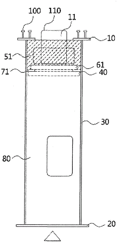
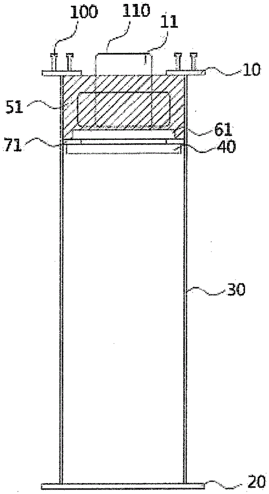
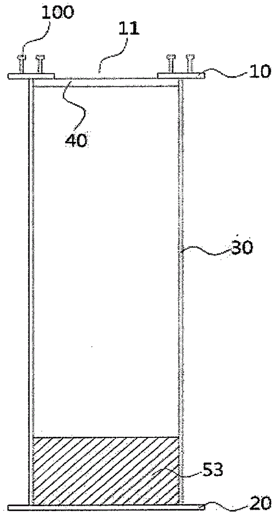
The invention relates to a combined box beam which comprises a netted steel box beam and upper part concrete (51) poured on the upper side inside the steel box beam; the steel box beam comprises a steel beam upper flange (10), a steel beam lower flange (20) and a steel web plate (30), wherein an opening area (11) is longitudinally formed in the center of the steel beam upper flange (10); the steel beam lower flange (20) is formed a certain distance away from the steel beam upper flange (10); the steel web plate (30) is connected with the two sides of the steel beam upper flange (10) and the two sides of the steel beam lower flange (20), and the height of the steel web plate (30) is greater than the width of the steel beam upper flange (10) and the width of the steel beam lower flange (20). The composite box beam provided by the invention has the following benefit that as the width of each of the steel beam upper flange (10) and the steel beam lower flange (20) of the steel box beam is less than the height of the web plate, and a mesh shape is formed, the steel consumption of the steel beam upper flange (10) and the steel beam lower flange (20) is reduced, and the quantity of reinforcing components longitudinally or transversely arranged inside a bridge is reduced, therefore, the steel consumption is greatly reduced, and the manufacturing process is simplified.

Description

【Technical Field】 [0001] The invention relates to a combined box beam. 【Background technique】 [0002] Generally speaking, in the past rectangular or trapezoidal steel box girder, the section between the positive and negative moments is a closed section composed of the upper and lower flanges of the beam and two webs. In the past technology, the cross-section is made into a square or rectangular shape with no big difference between the width of the upper and lower flanges of the beam and the height of the web. In order to maintain the shape of the steel box girder, it needs to be installed longitudinally or laterally inside the bridge A large number of reinforcement members, so the demand for steel is very large. In addition, in the compression area of ​​the lower flange of the steel box girder, the compression resistance is all borne by the tensile member, that is, steel. In the compression area of ​​the upper flange of the beam, the bottom plate bridge slab bears the compressi...

Claims


Application Information

Patent Timeline
Patent Type & Authority Applications(China)
IPC IPC(8): E01D2/04
Inventor 盧炅範盧又鉉安声镛安善福
Owner BEIJING DISHENG KECHUANG CONSTR ENGCO
Learn More