MEMS microphone testing mechanism

A microphone test, microphone technology, applied in the direction of electrical components, etc., can solve the problems of affecting test accuracy, increasing user purchase costs, poor versatility, etc., to achieve stable test results and high test accuracy

Inactive Publication Date: 2016-06-29
SUZHOU BOJI OPTOELECTRONICS TECH CO LTD
View PDF6 Cites 10 Cited by
  • Summary
  • Abstract
  • Description
  • Claims
  • Application Information

AI Technical Summary

Problems solved by technology

[0008] However, the existing MEMS microphone testing institutions can only test for one of the forward sound microphone or the rear sound microphone, etc.
If it is necessary to test various forms, it is necessary to purchase or manufacture a variety of MEMS microphone test institutions, which has poor versatility and increases the purchase cost of users
[0009] In addition, when using the conventional MEMS microphone testing mechanism to test the forward-sounding microphone or the back-sounding microphone, the microphones to be tested will be placed unequally due to various factors, which will affect the test accuracy and the test effect will also be unstable.
[0010] 2. The package airtightness of the MEMS microphone cannot be tested

Method used


Image

  • MEMS microphone testing mechanism
  • MEMS microphone testing mechanism
  • MEMS microphone testing mechanism

Examples


Embodiment Construction

[0051] The present invention will be further described in detail below in conjunction with the accompanying drawings and specific preferred embodiments.

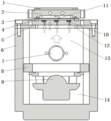
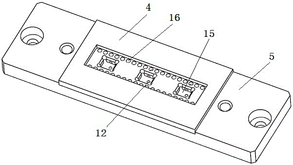
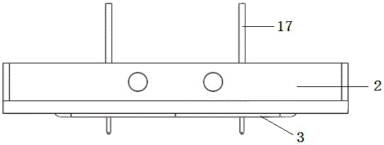
[0052] Such as figure 1 As shown, a MEMS microphone testing mechanism includes a testing acoustic cavity 6 , a product testing base 5 and a testing needle base 2 .

[0053] The test sound cavity is arranged under the product test base, and the top of the test sound cavity is preferably fixedly connected to the product test base by bolts. As an alternative, the top of the test sound cavity can also be fixedly connected to the product test base by other known connection methods such as snap-fitting and welding.

[0054] The above-mentioned test sound cavity can provide an external sound source for the MEMS microphone 10 to be tested. The MEMS microphone to be tested can be a back-feeding microphone or a forward-feeding microphone. The MEMS microphone testing mechanism of the present application can perform compatibility tes...


PUM


Abstract

The invention discloses a MEMS microphone testing mechanism comprising a testing vocal cavity, a product testing pedestal, and a testing needle seat. The testing vocal cavity is disposed on the lower part of the product testing pedestal, and is used to provide the external sound source for the MEMS microphone to be tested. The top part of the product testing pedestal is provided with a product accommodation groove, the bottom part of which is provided with central sound inlet holes, the peripheries of which are provided with peripheral sound inlet holes, and the outer peripheries of the peripheral sound inlet holes are provided with a first sealing structure. The height of the testing needle seat can be elevated. The bottom part of the testing needle seat is provided with a cavity and a second sealing structure. When the testing needle seat is lowered, the second sealing structure can be cooperated with the first sealing structure, and in addition, the upper part of the MEMS microphone to be tested can be provided with a second vocal cavity, which is communicated with the testing vocal cavity, and is sealed. By adopting the above mentioned structure, the universality is strong, and the vocal detection of the front inlet sound and the back inlet sound can be detected, and the production costs can be saved, and in addition, the accuracy of the testing result is high, and the testing result is more stable.

Description

technical field [0001] The invention relates to an electronic product testing mechanism, in particular to a MEMS microphone testing mechanism. Background technique [0002] Microphones can convert human voice signals into corresponding electrical signals, and are widely used in mobile phones, computers, telephones, cameras and video cameras, etc. [0003] MEMS microphones are microphones manufactured based on Microelectromechanical Systems (MEMS for short) technology. [0004] With the increasing development of IT technology, the proportion of MEMS microphones is increasing, especially in the multimedia audio and video applications of PCs and the 4G mobile phone applications that have already appeared, the input quality of audio signals and the ability to resist various external interferences. put forward higher requirements. Therefore, higher requirements are put forward for the acoustic testing of MEMS microphones. [0005] Existing MEMS microphone testing institutions ...

Claims


Application Information

Patent Timeline
Patent Type & Authority Applications(China)
IPC IPC(8): H04R29/00
CPCH04R29/00
Inventor 陈恕华
Owner SUZHOU BOJI OPTOELECTRONICS TECH CO LTD
Why Eureka
Try Eureka