Signal coverage control method and system of WiFi access point

A technology of signal coverage and control methods, applied in the field of communication, can solve problems such as poor user experience, failure to meet normal communication requirements, signal differences, etc., and achieve the effect of improving user experience

Inactive Publication Date: 2016-06-29
BEIJING QIHOO TECH CO LTD +1
View PDF5 Cites 6 Cited by
  • Summary
  • Abstract
  • Description
  • Claims
  • Application Information

AI Technical Summary

Problems solved by technology

[0003] Among them, in the way of omnidirectional antenna arrangement, the transmitted energy is relatively scattered. When other terminals connected to this device move to certain locations, the received signal may be poor, which cannot meet the normal communication requirements; the way of directional antenna arrangement The transmission energy is concentrated in a certain direction. When other terminals connected to this device are in the area radiated by the direction, the communication signal is better, but other terminals outside the area radiated by the direction will also appear due to weak signals. In case of failure to communicate normally
Therefore, although the communication device will always radiate a certain amount of energy when it is working normally, the signal received by the terminal connected to the communication device will be different due to the location or the energy radiation direction of the communication device. At the same time, there may be a strong signal in a certain area of ​​the radiation emission direction of the communication equipment, but there is no terminal connection, while in another area, there are terminals that cannot communicate normally because the received signal is weak; therefore, it does not realize resource allocation Reasonable allocation not only wastes some resources, but also makes the user experience poor

Method used


Image

  • Signal coverage control method and system of WiFi access point
  • Signal coverage control method and system of WiFi access point
  • Signal coverage control method and system of WiFi access point

Examples


Embodiment Construction

[0071] The present invention will be further described below with reference to the accompanying drawings and exemplary embodiments, examples of which are shown in the accompanying drawings, wherein the same or similar reference numerals represent the same or similar elements or elements with the same or similar functions . The embodiments described below by referring to the figures are exemplary only for explaining the present invention and should not be construed as limiting the present invention. Also, detailed descriptions of known arts will be omitted if they are unnecessary to illustrate the features of the present invention.

[0072] Those skilled in the art will understand that unless otherwise stated, the singular forms "a", "an", "said" and "the" used herein may also include plural forms. It should be further understood that the word "comprising" used in the description of the present invention refers to the presence of said features, integers, steps, operations, ele...


PUM


Abstract

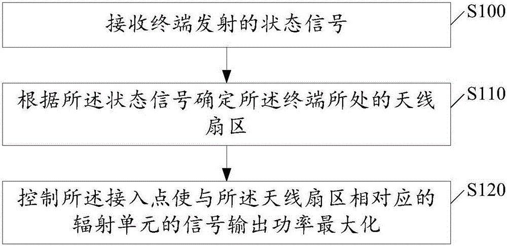
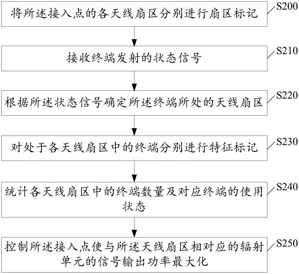
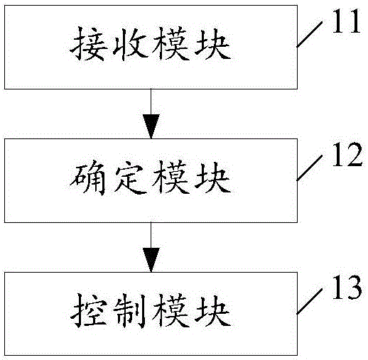
The invention relates to the technical field of communication, especially relates to a signal coverage control method and system of a WiFi access point. The method provided by the invention comprises following steps of receiving state signals transmitted by terminals; determining antenna sections in which the terminals are located according to the state signals; and controlling the access point so as to maximize the signal output powers with the radiation units corresponding to the antenna sections. Therefore, according to the method and the system, the antenna sections in which the terminals are located can be judged relatively accurately; the access point is relatively accurately controlled so as to adjust the signal output powers with the radiation units corresponding to the antenna sections in which the terminals are located; the terminals in the antenna sections are allocated and receive relatively rational network signal strengths; further the communication qualities of the terminals in the antenna sections are prevented from being influenced by the fact that the network signals in the corresponding antenna sections are relatively poor; the wastes of network signal resources and related resources can be reduced; and the use experience effects of the users are comprehensively increased.

Description

【Technical field】 [0001] The present invention relates to the field of communication technologies, in particular to a method and system for controlling coverage of WiFi access point signals. 【Background technique】 [0002] The antennas of existing communication devices (such as routers, mobile phones, base stations, etc.) all use omnidirectional or fixed directional antennas. In the omnidirectional antenna arrangement, the energy of the antenna is evenly distributed within the circular 360-degree range when the antenna is emitted, while In the method of fixedly arranging the antenna, when the antenna transmits, the energy is transmitted towards the fixed direction of the antenna. [0003] Among them, in the way of omnidirectional antenna arrangement, the transmitted energy is relatively scattered. When other terminals connected to this device move to certain locations, the received signal may be poor, which cannot meet the normal communication requirements; the way of direct...

Claims


Application Information

Patent Timeline
Patent Type & Authority Applications(China)
IPC IPC(8): H04W52/24
CPCH04W52/245
Inventor 李建波
Owner BEIJING QIHOO TECH CO LTD
Why Eureka
Try Eureka