A wire forming device

A wire rod and forming wheel technology, applied in the field of wire rod forming devices, can solve problems such as fatigue life reduction and wire rod surface damage, and achieve the effect of large meshing depth

Inactive Publication Date: 2016-06-29
BEKAERT BINJIANG STEEL CORD CO LTD
View PDF13 Cites 2 Cited by
  • Summary
  • Abstract
  • Description
  • Claims
  • Application Information

AI Technical Summary

Problems solved by technology

[0018] The inventors have observed that with known crimping devices a particular problem can occur: because the forming wheels rotate independently of each other and are separated by a gap, there is an angular "play" between the two forming wheels
The changing phase difference may also cause the wire to be partially caught between the teeth of the deformation wheel, resulting in damage to the wire surface
For wire ropes, a damaged wire surface is known to result in reduced fatigue life

Method used


Image

  • A wire forming device
  • A wire forming device
  • A wire forming device

Examples


Embodiment Construction

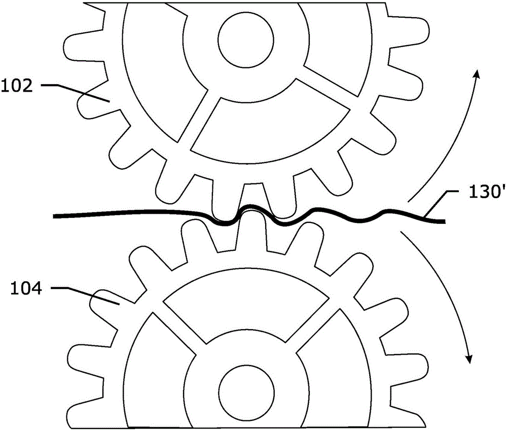
[0068] image 3 A first preferred embodiment of the inventive wire shaping device 300 is shown. It comprises a holder 310 in which deformation wheels 302 and 304 are mounted. Deformation wheels 302 and 304 are mounted on shafts 322 and 324, respectively. Bearings (not shown) for the deforming wheels are mounted in bearing housings 332, 332' and 334, 334' between the shafts 322, 324 and the holder 310, respectively. The top shaft 322 can be lowered or raised by means of set screws 318, 318', thereby adjusting the gap between the deformation wheels. A coiled wire 330' exists between the deformation wheels. Two slots 320, 320' are provided in the holder 310 to allow the top deformation axle to move parallel to the lower deformation axle.

[0069] The difference with prior art crimpers is the presence of a synchronous coupling coupling the rotational movement of the first and second deforming wheels. In this particular embodiment, the synchronous coupling takes the form of tw...


PUM


Abstract

A wire forming device (300) comprises a first and second deforming wheel (302,304) turnable on shafts (322, 324) in a holder (310), a synchronizing coupling (410) for coupling the first and second wheel such that the first and second deforming wheels are rotatable with synchronized circumferential speed at the gap between the first and second wheel. A composite wire forming device comprises two or more wire forming devices. A sawing wire can be formed by the composite wire forming device or the wire forming device. The wire forming device can be used to crimp wires, more particularly steel wires for use, in steel cord or as a sawing wire or as a brush wire. In this way the phase difference between the deforming wheels can be adjusted at will.

Description

technical field [0001] The invention relates to a wire shaping device for inducing impressions or bends in a wire, more particularly in a steel wire rope or on a steel wire used as saw wire or as brush wire. Background technique [0002] In many wire applications, it is beneficial to shape the wire in a specific shape. Mainly this is in the form of waves in a single plane, possibly combined with other deformations such as turns or bends or a second curl in a plane different from the plane of the first curl. [0003] The reasons why curl is introduced can be varied. For example in the field of reinforced steel cords for rubber products: [0004] • The monofilaments are crimped to influence the elongation behavior of the monofilaments in the rope. A coiled wire has a higher elongation at break and a lower modulus than a straight wire. Furthermore, these properties can be tuned quite well by tuning the magnitude and wavelength of the curl. [0005] • The monofilaments in t...

Claims


Application Information

Patent Timeline
Patent Type & Authority Applications(China)
IPC IPC(8): B21F1/04
CPCB21F1/04
Inventor K·范利塞尔伯吉李玲君
Owner BEKAERT BINJIANG STEEL CORD CO LTD
Why Eureka
Try Eureka