Large-flow combined linear screw pump

A technology of screw pump and high flow, which is applied in the direction of pumps, rotary piston pumps, liquid fuel engines, etc., and can solve problems such as increased sealing difficulty, loud noise, and reduced infusion efficiency

Inactive Publication Date: 2011-04-27
CHONGQING UNIV
View PDF4 Cites 6 Cited by
  • Summary
  • Abstract
  • Description
  • Claims
  • Application Information

AI Technical Summary

Problems solved by technology

At the same time, the engagement depth is one of the main reasons for increasing the liquid delivery rate. Theoretically, the deeper the engagement depth between the driving screw and the driven screw, the greater the liquid injection flow. However, a larger engagement depth will be the driving force. After the screw and the driven screw are meshed, due to the long meshing line in the radial section, the difficulty of sealing is increased, and the degree of sealing is reduced, so the infusion efficiency of the whole pump will be greatly reduced, resulting in a large loss of energy and a waste of driving energy. , at the same time, not only will the efficiency of the conveying medium be reduced, but also there will be greater noise during operation

Method used


Image

  • Large-flow combined linear screw pump
  • Large-flow combined linear screw pump
  • Large-flow combined linear screw pump

Examples


Embodiment Construction

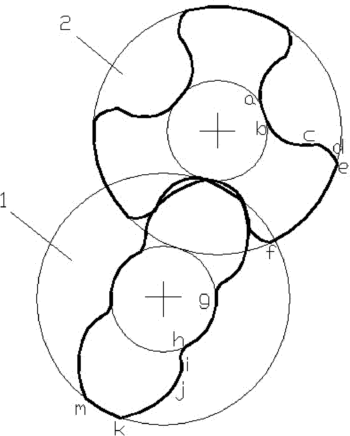
[0050] The accompanying drawing is a structural schematic diagram of the present invention, as shown in the figure: the large-flow combined linear screw pump of this embodiment includes a driving screw 1 and a driven screw 2 that are engaged with each other, and the driving screw 1 and the driven screw 2 are The radius of the top circle is greater than twice the radius of the root circle;

[0051] The tooth profile line of the radial section of the driving screw 1 is arc segment hi, involute segment ij and cycloid segment jk in turn from the tooth root to the tooth top;

[0052]The tooth profile line of the radial section of the driven screw 2 is the cycloid segment bc, the involute segment cd and the arc segment de from the tooth root to the tooth top;

[0053] As shown in the figure, on the driving screw, the root arc gj is connected with the arc segment hi, and the addendum arc km is connected with the cycloid segment jk, forming the entire tooth shape of the radial section...


PUM


Abstract

The invention discloses a large-flow combined linear screw pump having a structure that radiuses of tip circles of a driving screw and a driven screw are respectively greater than radiuses of root circles by two times and having greater engagement depth. Compared with the screw pump in the prior art, the area of the end face at the tooth end of the screw pump provided by the invention is large, that is to say, the work section area of the screw is increased and further the flow is increased at the same rotating speed; for adapting to greater engagement depth and maintaining the better sealing effect, tooth profile lines of the radial section of the driving screw sequentially include an arc segment, an involute segment and a cycloid segment from the tooth root to the tooth top; tooth profile lines of the radial section of the driven screw sequentially include a cycloid segment, an involute segment and an arc segment from the tooth root to the tooth top; and the tooth crest segments of the driving screw and the driven screw are in arc-arc engagement and the better sealing effect can be achieved, thereby the higher conveying efficiency can be obtained, driving energy sources can be saved, and the operation noise caused by the engagement gap can be reduced. The tooth profiles of the driving screw and the driven screen are more beneficial to the design of a molding cutter and the realization on high precision and high efficiency of the screw.

Description

technical field [0001] The invention relates to a screw pump, in particular to a screw pump with relatively large flow. Background technique [0002] The screw pump uses the rotation of the screw to suck and discharge the liquid. Screw pumps are divided into single screw pumps and multi-screw pumps. Multi-screw pumps generally include a driving screw and a driven screw that cooperates with it. The driving screw is driven by the prime mover to rotate, and the driven screw rotates in the opposite direction with the driving screw. [0003] The screw pump is divided into several sealed spaces between the suction port and the discharge port of the pump through the mutual meshing of the driving screw and the driven screw and the sealing fit between the screw and the inner wall of the liner. With the rotation and engagement of the screw, these sealed spaces are continuously formed at the suction end of the pump, sealing the liquid in the suction chamber, and continuously moving fr...

Claims


Application Information

Patent Timeline
Patent Type & Authority Applications(China)
IPC IPC(8): F04C2/16
Inventor 唐倩张元勋李忠华严迪
Owner CHONGQING UNIV
Why Eureka
Try Eureka