
Controlling a charging device by means of a storage battery

Inactive Publication Date: 2016-06-29
HILTI AG
View PDF5 Cites 2 Cited by
  • Summary
  • Abstract
  • Description
  • Claims
  • Application Information

AI Technical Summary

Problems solved by technology

[0005] However, as correspondingly disclosed in DE 10 2010 041 510, the disadvantage of the already existing system consisting of accumulator and charging device is that the user of the system is limited to a limited selection of predetermined charging processes or charging programs, which The process or charging program is stored in the battery and is used to regulate the entire charging process
Thus, there is only a small degree of flexibility for the charging of the accumulator
[0006] Furthermore, the problem with this system of accumulators and charging devices is that the older charging devices are no longer able to charge newer accumulators with new and significantly more complex charging procedures and charging algorithms, or only Can be recharged at a significant tech cost

Method used


Image

  • Controlling a charging device by means of a storage battery
  • Controlling a charging device by means of a storage battery

Examples


Embodiment Construction

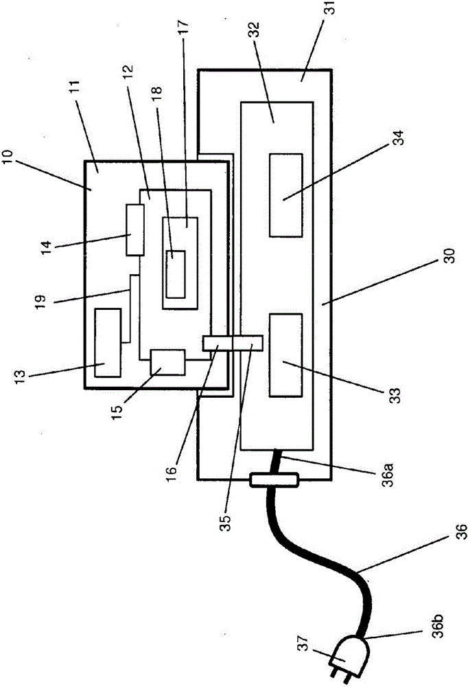
[0018] figure 1 A system 1 comprising a battery 10 and a charging device 30 is shown.

[0019] To this end, the accumulator 10 comprises a housing 11 , a control unit 12 , a temperature sensor 13 , a voltage sensor 14 , a current sensor 15 and an interface 16 facing a charging device 30 .

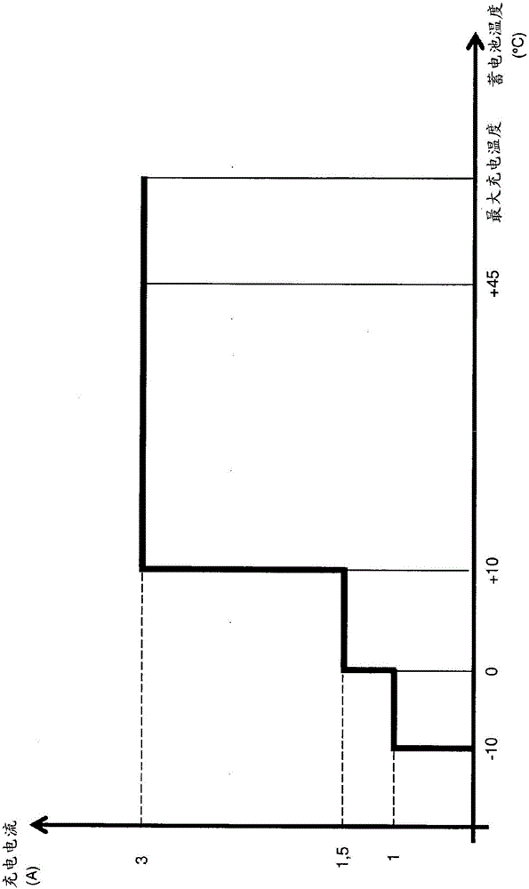
[0020] The control unit 12 of the accumulator 10 is located in the housing 11 of the accumulator 10 and in turn contains a microprocessor 17 and a memory unit 18 . A charging program specific to the accumulator 10 is stored on the memory unit 18 . In this case, the charging program contains characteristic curves, for example current-voltage characteristic curves. Furthermore, memory unit 18 also contains a characteristic diagram, in which at least one temperature value of battery 10 is introduced as a parameter into the current-voltage characteristic diagram. As a result, different temperature-dependent charging processes or charging programs are stored in battery 10 .

[0021] The micr...


PUM


Abstract

Disclosed is a method for controlling a charging process in a system containing a storage battery and a charging device, said method comprising the step of transmitting a control signal from the storage battery to the charging device, which can be connected to the storage battery, in order to adjust at least one charging parameter of the charging device.

Description

technical field [0001] The invention relates to a method for controlling a charging process in a system comprising an accumulator and a charging device. [0002] In order to charge the accumulator, the accumulator is connected to a charging device, so that the accumulator can again be supplied with current or voltage for storage in the accumulator. Background technique [0003] In hitherto known systems consisting of accumulator and charging device, the supply of current or voltage from the charging device to the accumulator takes place by means of so-called characteristic curves which are stored in a diagram of the charging device, that is to say in the charging device. on the control unit in the device. With the help of these diagrams and the corresponding identification of the connected battery, the charging device can supply suitable current or voltage values ​​(ie magnitude, duration, etc.) to the connected battery. [0004] Such a system consisting of a storage batte...

Claims


Application Information

Patent Timeline
Patent Type & Authority Applications(China)
IPC IPC(8): H02J7/00
CPCH01M10/4257Y02E60/10H02J7/007194H02J7/00034
Inventor K·豪泽B·贝克特
Owner HILTI AG
Learn More