Machine tool column boring and milling plane clamp

A technology of milling plane and column, applied in the field of machine tool fixture design, can solve the problems of large tool setting error, large processing limitation, time-consuming, etc., and achieve the effect of accurate tool setting position and avoiding interference.

Inactive Publication Date: 2016-07-06
安徽白鹰精密车床有限公司
View PDF0 Cites 3 Cited by
  • Summary
  • Abstract
  • Description
  • Claims
  • Application Information

AI Technical Summary

Problems solved by technology

[0003] The purpose of the present invention is to design a machine tool column in order to overcome the defects of the prior art, such as troublesome and time-consuming clamping of workpieces with traditional fixtures, large tool setting errors, difficult feed control, and large processing limitations when drilling the column hole of the machine tool. Drilling and milling plane fixture, easy installation of workpiece, accurate tool setting position, convenient control of processing feed, wide processing range

Method used


Image

  • Machine tool column boring and milling plane clamp
  • Machine tool column boring and milling plane clamp

Examples


Embodiment Construction

[0016] In order to make the technical means, creative features, goals and effects achieved by the present invention easy to understand, the present invention will be further described below in conjunction with specific illustrations.

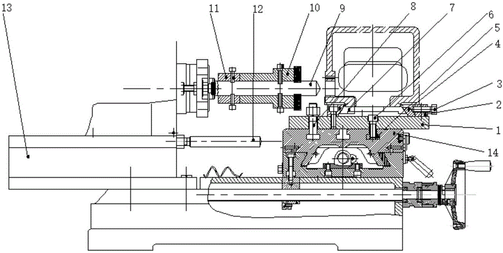
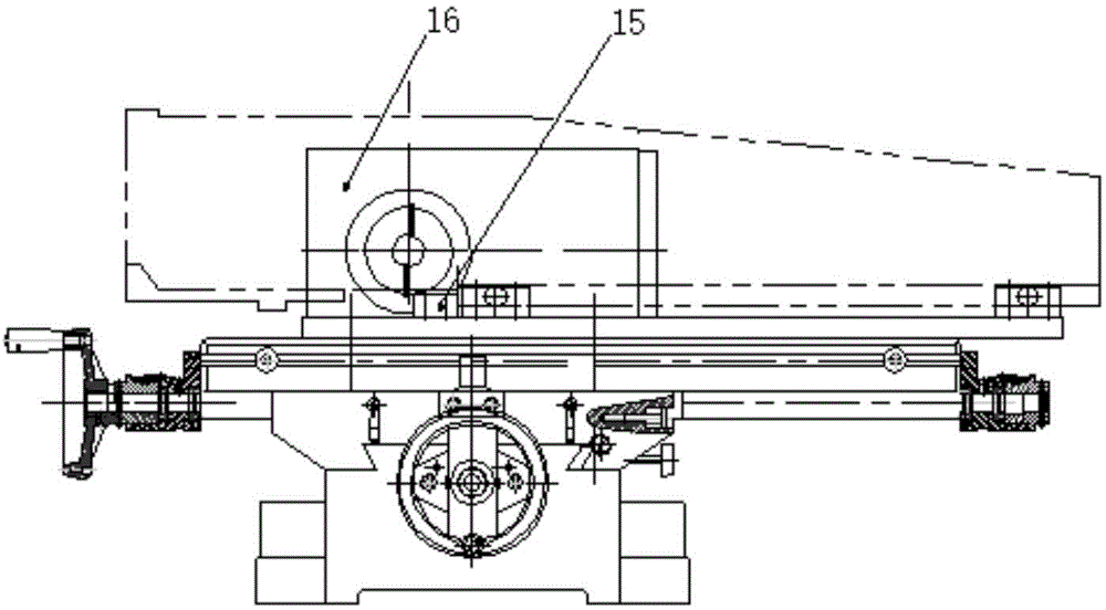
[0017] A fixture for drilling and milling a machine column, including a clamp body 1, a support block 2, a hexagonal head bolt 3, a bead 4, a T-shaped block 5, an inner hexagonal screw 6, a tool setting block 7, a T-shaped bolt 8, and a drill bit 9 , milling cutter head 10, guide sleeve 11, limit screw 12, connecting support seat 13, workbench 14, limit block 15, spindle box 16, clamp body 1 is fixed on the workbench 14 by T-shaped bolt 8, in the clamp Specifically, the right side of the upper surface of 1 is fixed with a support block 2, and the hexagon head bolt 3 is screwed into the support block 2, and a bead 4 is arranged on the left side of the support block 2, and the hexagon head bolt 3 can squeeze the bead 4 to compress the workpiece. ,...


PUM


Abstract

The invention discloses a machine tool column boring and milling plane clamp, and belongs to the machine tool clamp design technical field; the machine tool column boring and milling plane clamp comprises a clamp body, a support block, a hexagon bolt, a press bar, a T-shape block, an inner hexagonal screw, a feeler block, a T-shape bolt, a drill bit, a facing cutter, a guide sleeve, a limit screw rod, a connecting support seat, a work table, a limit block and a main shaft box; the clamp body is fixed on the work table; the support block is fixed on the clamp body; the left side of the support block is provided with the press bar; the top surface of the clamp body is provided with a feeler block; the connecting support seat is arranged on the left side of the work table; the main shaft box is fixed on the connecting support seat; the drill bit is clamped in a chuck on the right side of the main shaft box; the drill bit is sleeved by the guide sleeve; the guide sleeve is fixed on the drill bit by a screw; the facing cutter is arranged on the right side of the guide sleeve. The machine tool column boring and milling plane clamp is convenient in workpiece installation, cutter tool setting is accurate in positioning, processing feed amount is convenient in control, and processing scope is wide.

Description

technical field [0001] The invention relates to the technical field of machine tool fixture design, in particular to a machine tool column drilling and plane milling fixture. Background technique [0002] With the development of the machinery industry, the requirements for the shape of the parts vary widely. Different shapes of workpieces must be processed on the machine tool using different clamping methods. For example, when drilling the column hole of the machine tool, the traditional processing method is first on the drilling machine. Drilling, and then switching to the milling machine to mill the plane, the workpiece clamping is cumbersome and time-consuming. There is no tool setting device and limit device on the traditional fixture, which makes the tool setting error large, and the processing feed is difficult to control. Manual control is harmful to workers. The technical level is high, and the limitations of traditional machine tool processing are large. Therefore, ...

Claims


Application Information

Patent Timeline
Patent Type & Authority Applications(China)
IPC IPC(8): B23Q3/06B23P23/02
Inventor 常青
Owner 安徽白鹰精密车床有限公司
Why Eureka
Try Eureka