
Vehicle escaping and self-help device and vehicle escaping and self-help method

A technology for vehicles and spindles, which is applied to vehicle control devices, vehicle maintenance, and shunting equipment, etc., can solve the problems of time-consuming, expensive, and inability to install, and achieve the effects of wide application range, low price, and easy installation.

Inactive Publication Date: 2016-07-06
罗熙宏 +1
View PDF7 Cites 8 Cited by
  • Summary
  • Abstract
  • Description
  • Claims
  • Application Information

AI Technical Summary

Problems solved by technology

[0002] All wheeled motor vehicles are faced with the situation that the four wheels slip or the torque is insufficient due to the vehicle being stuck on various complex roads such as wet slippery mud and steep slopes, and the driving force is lost. The traditional self-rescue method is to install a special vehicle winch and use the vehicle The battery drives the motor to generate traction to free the vehicle
In the past, the traditional winch self-rescue method was expensive and had to be installed on the front or rear of the motor vehicle, which increased the load on the vehicle. At the same time, many cars could not be installed at all, and the service life of the vehicle battery was greatly damaged during use. Therefore, installing an electric winch is not the best way to save yourself when a wheeled vehicle is trapped
Although there are also technical solutions for using the driving wheel as the power of the winch, without exception, there are defects such as refitting and dismantling of the vehicle components, complicated structure, and time-consuming and laborious installation.

Method used


Image

  • Vehicle escaping and self-help device and vehicle escaping and self-help method
  • Vehicle escaping and self-help device and vehicle escaping and self-help method
  • Vehicle escaping and self-help device and vehicle escaping and self-help method

Examples


Embodiment Construction

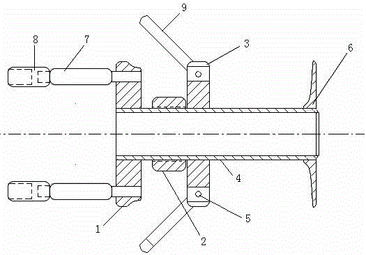
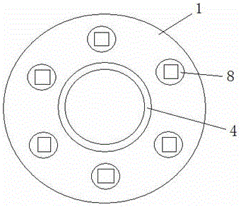
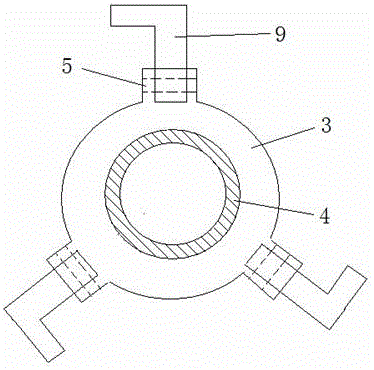
[0015] See figure 1 —— image 3 The vehicle escape self-rescue device provided by the present invention comprises a main shaft 4, a base 1 and a cover 6 arranged at the front and rear ends of the main shaft 4, a slider 3 sleeved in the middle of the main shaft 4 and slides along the main shaft 4, and set on the main shaft 4. Between the base 1 and the slider 3 and the adjusting nut 2 threadedly engaged with the main shaft 4, the base 1 is axially provided with several sleeves for cooperating with the nuts on the fixed hub of the vehicle through the connecting rod 7 8. The slider 3 is provided with three circumferentially arranged dragon claws 9 for axially buckling on the hub, and the dragon claws are hinged on the slider 3 through a hinge 5 .

[0016] The device of the present invention can be used for self-rescue of vehicles. When the wheels of the vehicle slip and get stuck, the device of the present invention can be installed on the hubs of the driving wheels on both side...


PUM


Abstract

The invention discloses a vehicle escaping and self-help device and a vehicle escaping and self-help method. The vehicle escaping and self-help device comprises a main shaft, a base, a retaining cover, a sliding block, and an adjusting nut, wherein the base and the retaining cover are arranged at the front end and the rear end of the main shaft; the sliding block sleeves the middle of the main shaft and slides along the main shaft; the adjusting nut is arranged between the pedestal and the sliding block and is in threaded match with the main shaft; a plurality of sleeves matched with caps for fixing wheel hubs on the vehicle are axially arranged on the pedestal; at least two claws are arranged on the sliding block and used for axially fastening a wheel hub. The vehicle escaping and self-help device is driven by power output of a motor vehicle wheel, enables the vehicle to be drawn by the traction of a rope directly to carry out self-help under the situation that the friction force between the tire and the ground cannot allow the vehicle to escape out, so as to enable the vehicle to escape out easily. The vehicle escaping and self-help device has the characteristics of being simple and convenient to mount, low in price, effective in usage, wide in application range, and free of damage to the vehicle, and can be used for enabling various wheel vehicles trapped in complicated roads to escape out conveniently and quickly.

Description

technical field [0001] The invention belongs to a vehicle rescue device, in particular to a vehicle self-rescue device and a vehicle self-rescue method. Background technique [0002] All wheeled motor vehicles are faced with the situation that the four wheels slip or the torque is insufficient due to various complex roads such as wet slippery mud and steep slopes, and the traditional self-rescue method is to install a special on-board winch and use the on-board The battery drives the motor to generate traction to free the motor vehicle. In the past, the traditional winch self-rescue method was expensive and had to be installed on the front or rear of the motor vehicle, which increased the load on the vehicle. At the same time, many cars could not be installed at all, and the service life of the vehicle battery was greatly damaged during use. Therefore, installing an electric winch is not the best way to save yourself when a wheeled motor vehicle is trapped. Although there ...

Claims


Application Information

Patent Timeline
Patent Type & Authority Applications(China)
IPC IPC(8): B60S13/00
CPCB60S13/00
Inventor 罗熙宏罗梦
Owner 罗熙宏
Learn More