Automatic separator for needles of infusion apparatus

A technology of automatic separation and infusion set, which is applied in the direction of waste collection and transfer, garbage collection, household appliances, etc., and can solve problems such as needle stick injuries, medical staff's physical and mental damage, occupational safety, and heavy workload in wards.

Active Publication Date: 2016-07-06
JIAXING NO 1 HOSPITAL
View PDF7 Cites 11 Cited by
  • Summary
  • Abstract
  • Description
  • Claims
  • Application Information

AI Technical Summary

Problems solved by technology

[0002] In clinical nursing work, infusion is the most basic, most common, and most intensive nursing operation. According to the requirements of hospital infection management, in order to avoid environmental pollution and re-spreading diseases, disposable infusion sets should be destroyed on the spot after use. Clinical nursing staff Manual separation of the infusion needle is often used, and the needle of the infusion set is cut off manually with scissors and put into the sharps box, which may easily cause needle stick injury during operation
In most hospitals, the medical treatment room is too far away from the work place, the workload of the ward is heavy, and the operation time is insufficient. In order to save time, the nurses concentrate the sharp tools for secondary treatment.
Once a needlestick injury occurs, it is easy to cause medical staff to be infected with blood-borne pathogens, which will bring a series of problems such as physical and mental damage to medical staff and occupational safety.

Method used


Image

  • Automatic separator for needles of infusion apparatus
  • Automatic separator for needles of infusion apparatus
  • Automatic separator for needles of infusion apparatus

Examples


Embodiment Construction

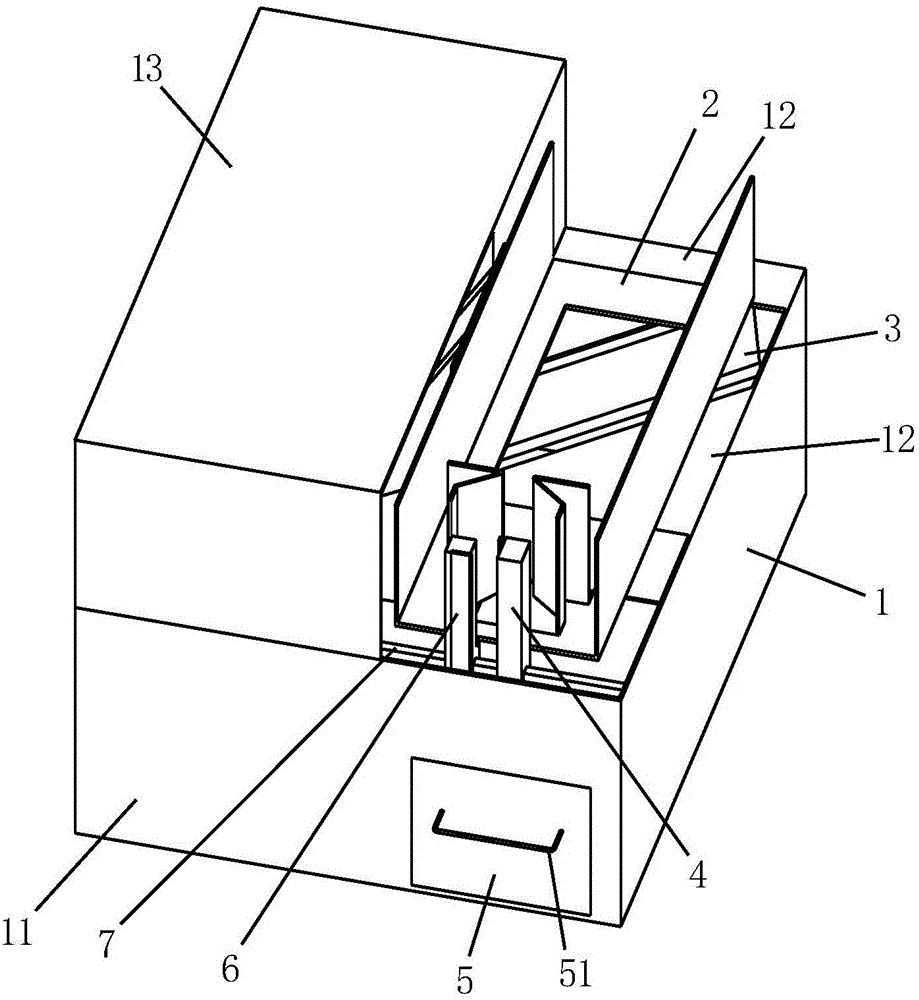
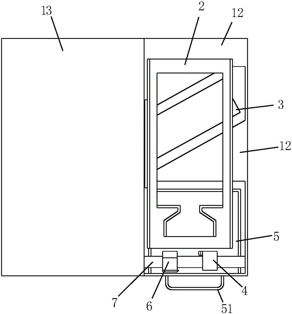
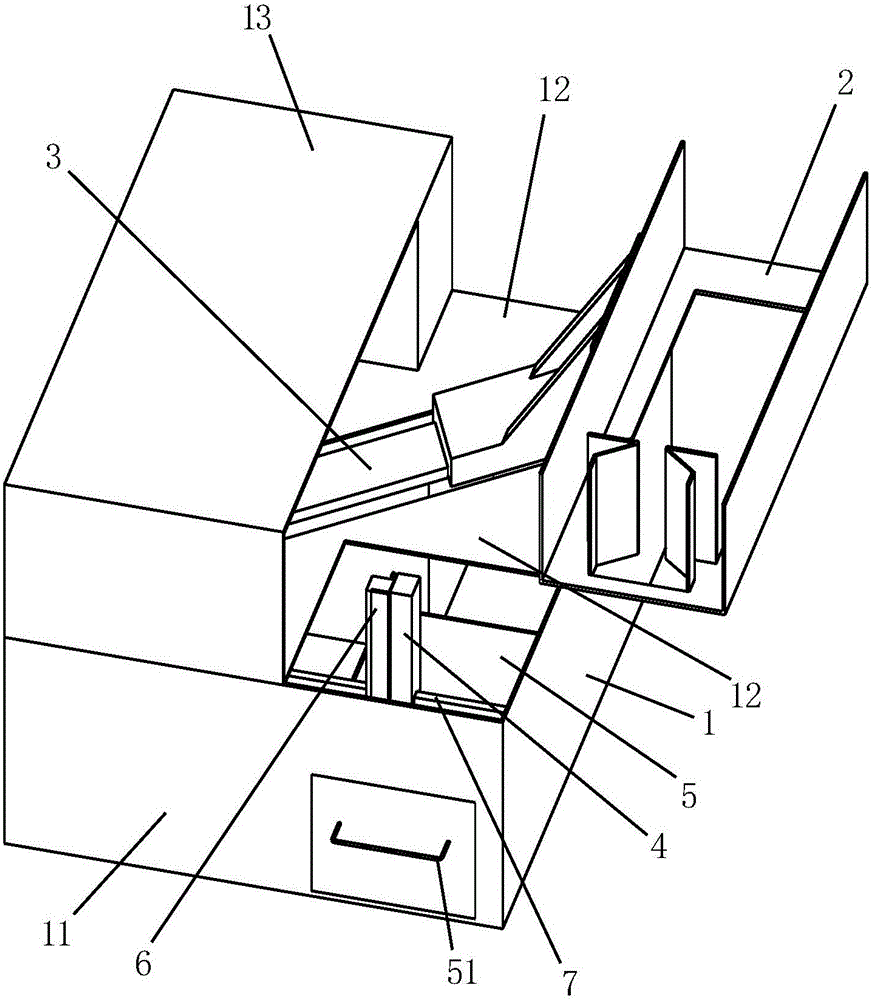
[0020] Such as figure 1 , figure 2 and image 3 As shown, this automatic needle separation machine for infusion sets includes a square housing 1, an infusion bag placement plate 2, a main slide rail 3, a blade assembly 6, a blade stopper 4, a sharps collection box 5 and an auxiliary slide rail 7, the main Both the slide rail and the auxiliary slide rail are arranged in the casing, and the transfusion bag placement plate, the blade assembly and the blade stopper are located above the casing. The main slide rail 3 and the auxiliary slide rail 7 are all parallel to the bottom surface of the housing 1, such as Figure 4 As shown, the auxiliary slide rail 7 is located at the rear side of the front side 11 of the housing and is parallel to the front side 11. The main slide rail 3 is obliquely placed in the housing, and the left end 31 of the main slide rail is located at the front of the housing. The right end 32 of the rail is located at the rear of the housing. Such as Figu...


PUM


Abstract

The invention relates to an automatic separator for needles of an infusion apparatus. The automatic separator comprises a shell (1), an infusion bag holding plate (2), a primary sliding rail (3), a blade assembly (6), a blade baffle plate (4), a sharp instrument collecting box (5) and an auxiliary sliding rail (7); the primary sliding rail obliquely is arranged in the shell; the infusion bag holding plate obliquely slides along the primary sliding rail. A rectangular hole (24) is formed in the middle of a bottom plate (21) of the infusion bag holding plate, and two infusion bag baffle plates (25) are symmetrically positioned at the rear side of the front edge of the rectangular hole in the bottom plate; the blade baffle plate is fixed on the auxiliary sliding rail; the blade assembly comprises a blade (61) and a blade fixing block (62), wherein the blade fixing block is sheathed on the auxiliary sliding rail by virtue of a sliding chute in the lower end. The infusion bag holding plate and the blade assembly can be driven by a stepping motor and controlled by a singlechip, such that the whole operation process of cutting an infusion needle, a liquid guide needle and an air needle from an infusion hose, pulling the liquid guide needle and the air needle out of a bottle opening of the infusion bag, and the like can be automatically finished.

Description

technical field [0001] The invention relates to a medical auxiliary equipment, a structure of an automatic needle separation machine for an infusion set. Background technique [0002] In clinical nursing work, infusion is the most basic, most common and most intensive nursing operation. According to the requirements of nosocomial infection management, in order to avoid environmental pollution and re-transmission of diseases, disposable infusion sets should be destroyed on the spot after use. Manual separation of the infusion needles is often adopted, and the needles of the infusion set are manually cut off with scissors and put into the sharps box, which may easily cause needle stick injuries during operation. In most hospitals, the medical treatment room is too far away from the work place, the workload of the ward is heavy, and the operation time is insufficient. In order to save time, the nurses concentrate the sharp tools for secondary treatment. . Once a needlestick i...

Claims


Application Information

Patent Timeline
Patent Type & Authority Applications(China)
IPC IPC(8): B65F1/16B65F1/14B65F1/00
CPCY02W30/10B65F1/16B65F1/00B65F1/14B65F2001/1653B65F2210/126
Inventor 马娟妹杨明峰徐惠
Owner JIAXING NO 1 HOSPITAL
Why Eureka
Try Eureka