Valve management optimization method based on steam distribution mode switchover for 200MW heat supply unit

A steam distribution method and heating unit technology, applied in mechanical equipment, engine components, engine control, etc., can solve the problems of not considering the optimal valve position, the efficiency of the high-pressure cylinder of the steam turbine cannot be optimized, etc., and achieve the improvement of the efficiency of the high-pressure cylinder , Improving the efficiency of high pressure cylinders and overcoming the effect of insufficient data

Active Publication Date: 2016-07-06
HARBIN INST OF TECH +2
View PDF4 Cites 8 Cited by
  • Summary
  • Abstract
  • Description
  • Claims
  • Application Information

AI Technical Summary

Problems solved by technology

[0010] The present invention aims to solve the problem that the current steam distribution optimization scheme for 200MW heating units does not consider the influence of the deviation of the optimal valve position due to the change of steam extraction volume, that is, the same steam distribution optimization curve is used under different steam extraction volumes, and the high-pressure cylinder of the steam turbine The problem that the efficiency cannot be optimal, and then a valve management optimization method for the 200MW heating unit based on the switching of steam distribution mode is proposed

Method used


Image

  • Valve management optimization method based on steam distribution mode switchover for 200MW heat supply unit
  • Valve management optimization method based on steam distribution mode switchover for 200MW heat supply unit
  • Valve management optimization method based on steam distribution mode switchover for 200MW heat supply unit

Examples


specific Embodiment approach 1

[0032] Specific implementation mode one: combine Figure 1 to Figure 4 To illustrate this embodiment, the valve management optimization method for a 200MW heating unit based on the switching of the steam distribution mode described in this embodiment is realized through the following steps:

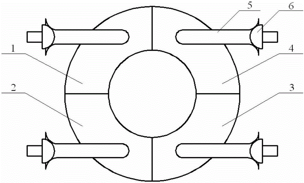
[0033] Step 1. According to the actual situation of the power plant equipment, set two steam distribution methods: the set steam distribution method is diagonal steam distribution, and the setting principle is: the first valve group is two diagonal valves, and the second valve group is another The lower cylinder valve, the third valve group is another upper cylinder valve;

[0034] Step 2. Carry out load-up and down-load experiments on the heating unit, obtain relevant experimental data, and calculate the efficiency of the high-pressure cylinder of the unit under different steam distribution methods:

[0035] The high pressure cylinder efficiency is defined as where the main steam enth...

specific Embodiment approach 2

[0047] Specific implementation mode two: combination Figure 1 to Figure 4 To illustrate this embodiment, the two steam distribution methods in Step 1 of the valve management optimization method for a 200MW heating unit based on the switching of steam distribution methods described in this embodiment are:

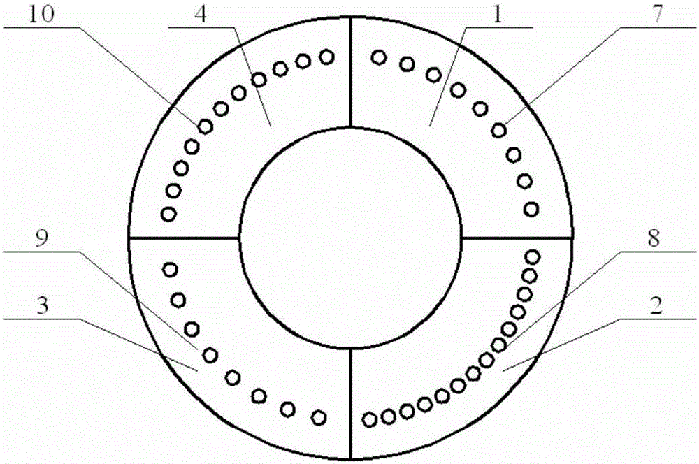
[0048] The first steam distribution method: the first valve group is No. 1 valve 1 and No. 3 valve 3, the second valve group is No. 2 valve 2, and the third valve group is No. 4 valve 4;

[0049] The second steam distribution method: the first valve group is No. 2 valve 2 and No. 4 valve 4, the second valve group is No. 1 valve 1, and the third valve group is No. 3 valve 3.

[0050] The efficiency curve of the high-pressure cylinder is calculated by using the temperature and pressure of the main steam and the exhaust temperature and pressure data of the high-pressure cylinder collected in the load-up and down-load tests under the above two steam distribution methods.

[00...

Embodiment

[0057] Combining with the transformation example of a 200MW heating unit and Figure 4 to Figure 10 The steam distribution mode switching method is described. The two steam distribution modes in Step 1 of the steam distribution mode switching based valve management optimization method for 200MW heating units described in the implementation mode are:

[0058] The first steam distribution method: the first valve group is No. 1 valve 1 and No. 3 valve 3, the second valve group is No. 2 valve 2, and the third valve group is No. 4 valve 4;

[0059] The second steam distribution method: the first valve group is No. 2 valve 2 and No. 4 valve 4, the second valve group is No. 1 valve 1, and the third valve group is No. 3 valve 3.

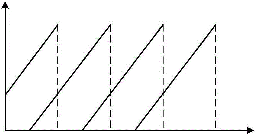
[0060] Use the above two steam distribution methods to do load lifting and lowering tests. The specific experimental process is as follows: Figure 5a and Figure 5b As shown, the valve opening sequence diagrams of the two steam distribution methods are as...


PUM


Abstract

The invention discloses a valve management optimization method based on steam distribution mode switchover for a 200MW heat supply unit. The invention relates to a switchover method, and specifically relates to a valve management optimization method based on steam distribution mode switchover for a 200MW heat supply unit. The invention aims at solving the problem that the influence of deflection of the optimal valve site due to the change of a steam extraction flow is not considered in the present steam distribution optimization scheme for a 200MW heat supply unit, that is, the same steam distribution optimization curve is adopted under different steam extraction flows, so that the efficiency of a high-pressure cylinder of a steam turbine cannot achieve the optimal value. The method disclosed by the invention comprises the following specific steps: setting two steam distribution modes according to the actual condition of power plant equipment; carrying out load-up and load-down experiments on the heat supply unit to obtain related experiment data, and calculating the efficiency of a high-pressure cylinder of the unit under the different steam distribution modes; obtaining the switchover boundaries of the steam distribution modes according to the efficiency curves of the high-pressure cylinder under the different steam distribution modes; determining the corresponding steam distribution mode according to the relative flow of main steam; and judging whether the change of the flow of the main steam exceeds a margin or not. The invention belongs to the field of steam turbine power generation.

Description

technical field [0001] The invention relates to a switching method, in particular to a valve management optimization method of a 200MW heating unit based on switching of steam distribution modes, and belongs to the field of steam turbine power generation. Background technique [0002] A steam turbine is a rotating machine powered by steam and converts the energy of steam into mechanical work. It is widely used in modern large-scale power generation systems. In order to meet the user's actual demand for electricity consumption, the steam turbine must frequently adjust its power to keep the motor power in balance with the changing load of the outside world. The most direct and effective way to change the power of the steam turbine is to control its steam intake. When the steam intake changes, the power of the steam turbine will also change accordingly, that is, the steam distribution of the steam turbine. [0003] Generally speaking, there are two ways to distribute steam to ...

Claims


Application Information

Patent Timeline
Patent Type & Authority Applications(China)
IPC IPC(8): F01D17/00
CPCF01D17/00F05D2270/16F05D2270/20
Inventor 李兴朔刘利平杨彦卿赵利军夏传弟任伟刘金龙李永生赵新宇江飞孙建国程江南李飞刘智万杰于达仁
Owner HARBIN INST OF TECH
Why Eureka
Try Eureka