
A miniature single-coil driven self-locking valve

A single-coil, micro-miniature technology, applied in valve devices, valve details, engine components, etc., can solve the problems of complex production process, complex connection, difficult application, etc., and achieve the effect of reducing weight and volume

Active Publication Date: 2018-06-19
BEIJING INST OF CONTROL ENG
View PDF7 Cites 0 Cited by
  • Summary
  • Abstract
  • Description
  • Claims
  • Application Information

AI Technical Summary

Problems solved by technology

[0004] In addition, the current high-performance electric valves usually adopt the flexible suspension design of the armature, and its core component is a sheet-shaped membrane spring. This structure generally has a large number of parts, more than 5, and the connection is complicated. Usually, electron beam welding or laser welding is required. and other processes, the production process is complicated
More importantly, the leaf film spring is limited by processing factors, and it is difficult or even impossible to apply it to valves with small radial dimensions, such as radial dimensions < 10mm.

Method used


Image

  • A miniature single-coil driven self-locking valve
  • A miniature single-coil driven self-locking valve
  • A miniature single-coil driven self-locking valve

Examples


Embodiment 1

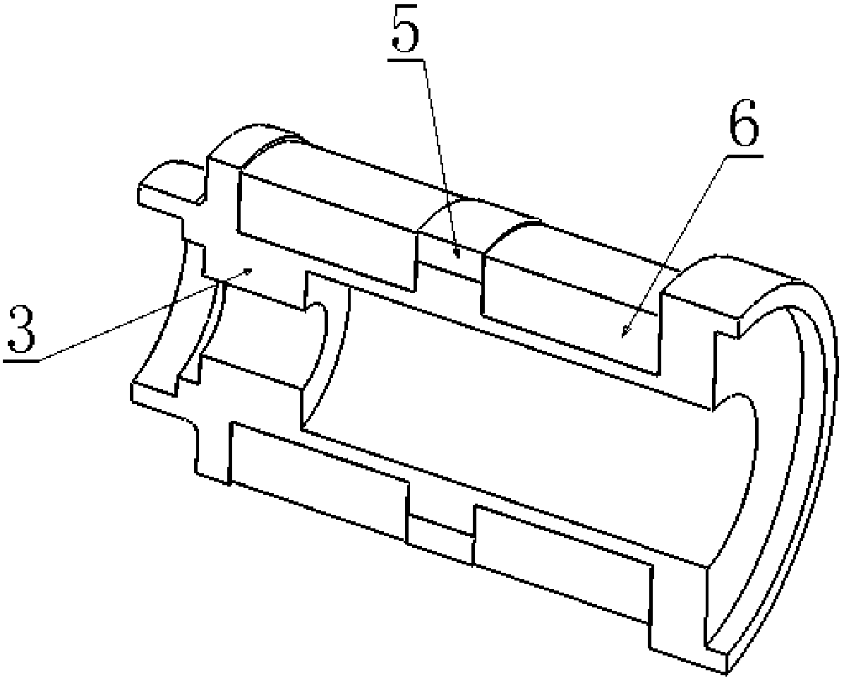
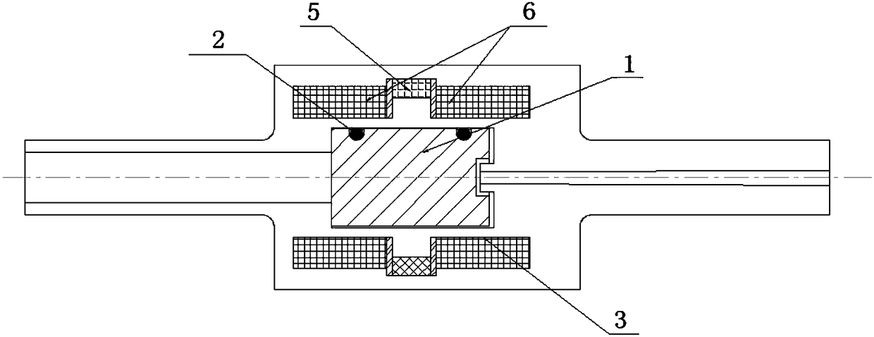
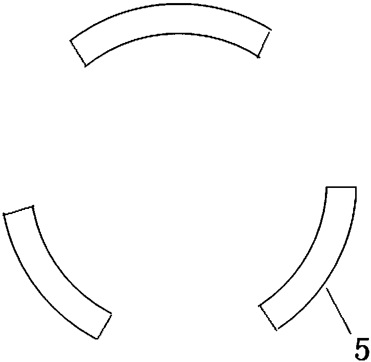
[0049] The magnetic steel 5 is set on the peripheral surface of the valve body 3, and divides the peripheral surface of the valve body 3 into two regions. Two coils 6 are respectively wound in the two regions and connected in series to form a coil with 800 turns. The magnetic steel 5 surrounds the surface of the valve body 3 and is divided into 3 sections of magnetic steel with the same arc size, and the 3 sections of magnetic steel are evenly distributed around the surface of the valve body 3, and the arc of each section of magnetic steel is 60°, such as image 3 shown. The magnetic steel 5 is arranged at the middle position of the valve body along the axial direction of the valve body 3 , and the width of the magnetic steel 5 along the axial direction of the valve body 3 is 2 mm. The two coils 6 on both sides of the magnetic steel 5 are connected in series at the gap between two adjacent sections of the magnetic steel to form a coil.

[0050] Such as Figure 4 a. Figure ...


PUM


Abstract

The invention relates to a miniature single-coil driven self-locking valve, which includes an armature assembly, a valve body, a magnetic steel and a coil. The armature assembly is arranged in the inner cavity of the valve body. The armature assembly includes an armature and a ball. It is a revolving body structure, and there are N grooves uniformly distributed along the circumference in the circumferential direction of the end faces of the armature close to both ends, and a ball is set in each groove, and the shape of the groove is a hollow spherical segment and a cylinder. Combined shape, the diameter of the spherical segment is the same as that of the cylinder, and the diameter of the ball is smaller than the diameter of the spherical segment or the cylinder in the groove, and greater than the depth of the groove. The magnetic steel is set on the circumferential surface of the valve body, and the circumferential surface of the valve body Divided into two areas, two coils are respectively wound in the two areas and connected in series to form a coil. The structural design of the self-locking valve greatly reduces the weight and volume of the product, reduces the number of parts, and realizes the miniaturization of the product. While optimizing the design, it also ensures the high reliability and fast response characteristics of the product.

Description

technical field [0001] The invention relates to a miniature single-coil driven self-locking valve, which belongs to the technical field of spacecraft space fluid management. Background technique [0002] Due to the small size and weight of the micro-nano satellite, the self-locking valve is used as the management valve of the propulsion system. It mainly realizes the on-off control of the propellant in the system. It is one of the important components of the system. The proposed weight requirement is generally below 50g or even 30g. [0003] Traditional self-locking valves generally use two coils to realize the driving control of the two states of valve opening and closing respectively. At the same time, in order to ensure the reliability of the product, flexible support elements are generally used for suspension support at both ends of the armature. The number of such structural parts is relatively small. Many, the structure is more complicated, and it cannot be realized i...

Claims


Application Information

Patent Timeline
Patent Type & Authority Patents(China)
IPC IPC(8): F16K31/06
CPCF16K31/0675F16K31/06F16K31/0651F16K31/0658F16K31/0679H01F2007/163H01F2007/1692
Inventor 苟浩亮张兵刘晖李栋王振鲁沈岩陈君惠欢欢曾召奇李永平王振兴王新慧孙超吴耀武宋新河
Owner BEIJING INST OF CONTROL ENG
Learn More