Light distribution lens and lighting device adopting same

A light distribution lens and lens technology, which is applied in the field of optical lenses, can solve the problems of large optical aperture and optical height of the lens structure, weak control ability of light and large-angle light, and difficulty in ensuring lighting effects, etc., to achieve uniform wall thickness and ensure design Lighting effect, effect of good lighting effect

Inactive Publication Date: 2016-07-06
CHENGDU HERCULUX OPTOELECTRONICS TECH CO LTD
View PDF5 Cites 5 Cited by
  • Summary
  • Abstract
  • Description
  • Claims
  • Application Information

AI Technical Summary

Problems solved by technology

[0007] The purpose of the present invention is to provide a lens capable of controlling the central part of the light and large-angle light, and the optical aperture and optical height of the lens structure are large, resulting in increased material costs and difficult to ensure the lighting effect of the design. Improve the light control ability of the central part, reduce the optical aperture and optical height of the lens, thereby reducing the cost of materials, reduce the difficulty of injection molding and the risk of shrinkage, and ensure the lens structure of the design lighting effect

Method used


Image

  • Light distribution lens and lighting device adopting same
  • Light distribution lens and lighting device adopting same
  • Light distribution lens and lighting device adopting same

Examples


Embodiment 1

[0041] Embodiment 1: as Figure 1-4 as shown,

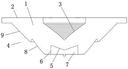
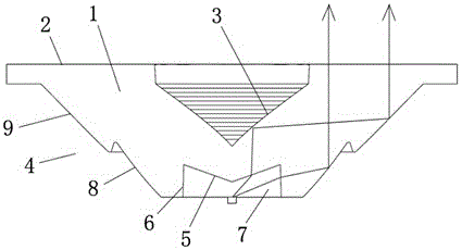
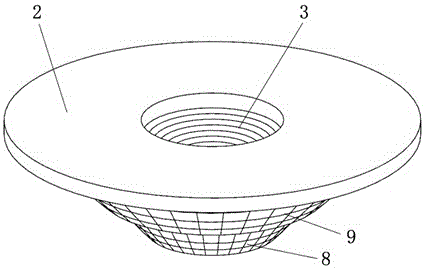
[0042] An LED light distribution lens, including a lens body 1, the lens body 1 is provided with an incident area 7 for light entering the interior of the lens, a light exit area 2 for emitting light inside the lens, and a In the reflection area 4 between the areas 2, the lens body 1 is also provided with a central reflection area 3. In the light emitted by the light source, the light in the central part is a small-angle light, and the light in the peripheral part of the light is a large-angle light. The small-angle light is refracted from the incident area 7 into the lens body 1 and then directly irradiates on the central reflection area 3, is reflected by the central reflection area 3 to the reflection area 4, is reflected by the reflection area 4 to the light output area 2, and then refracted Out of the lens body 1, at least a part of the large-angle light is refracted from the incident area 7 into the lens body 1 and directl...

Embodiment 2

[0049] Example 2, such as Figure 1-4 as shown,

[0050] The incident area 7 includes a first incident area 5 and a second incident area 6. The small-angle light rays enter the lens body 1 from the first incident area 5 and then irradiate on the central reflection area 3; the large-angle light rays pass through the second incident area. 6 enters the lens body 1 and irradiates on the reflection area 4 .

[0051] In the above scheme of this embodiment, the incident area 7 is set to include the first incident area 5 and the second incident area 6, the central part of the light emitted by the light source, that is, the small-angle light is irradiated on the first incident area 5, and the large Angled light irradiates on the second incident region 6, and the small-angle and large-angle parts of the light emitted by the light source are refracted into the lens through different regions, which further improves the light control ability of the lens structure of this embodiment.

[0...

Embodiment 3

[0055] Example 3, such as Figure 1-4 as shown,

[0056] The reflective area 4 includes a first reflective area 8 and a second reflective area 9 arranged in a stepped structure, the first reflective area 8 is close to the incident area 7, the second reflective area 9 is close to the light output area 2, and small-angle light rays Reflected from the central reflection area 3 to the second reflection area 9, and then reflected to the exit area by the second reflection area 9; after the large-angle light is refracted from the second incident area 6 into the lens body 1, it is irradiated on the first On the reflective area 8, it is reflected by the first reflective area 8 to the output area.

[0057] In the above solution, the reflective area 4 includes the first reflective area 8 and the second reflective area 9, which control the small-angle light and the large-angle light entering the lens respectively, further improving the control ability of the lens structure on the light, ...


PUM


Abstract

The invention relates to the technical field of optical lenses, in particular to a light distribution lens. A lens body is provided with a central reflection area; at least a part of small-angle light beams is refracted by an incidence area for entering the lens body, then directly irradiates the central reflection area, is reflected to a reflection area through the central reflection area, is reflected to a light exiting area through the reflection area and finally is refracted out of the lens body; at least a part of wide-angle light beams is refracted by the incidence area for entering the lens body, then directly irradiates the reflection area, is reflected to the light exiting area by the reflection area and is finally refracted out of the lens body. According to the light distribution lens, the small-angle light beams and the wide-angle light beams can be respectively controlled, the ability to control the small-angle light beams and the wide-angle light beams can be improved, and the design illumination effect of lens structures can be reliably guaranteed.

Description

technical field [0001] The invention relates to the technical field of optical lenses, in particular to a light distribution lens and an illuminating device using the light distribution lens. Background technique [0002] In the field of lighting technology, in order to distribute the light emitted by the light source according to people's needs, it is usually necessary to use various light conversion devices to reflect, refract, gather, or diverge the light, thus changing the propagation path of the light , and finally get a lighting area that meets people's actual needs. [0003] In the current light conversion device, the lens is widely used. The reason is that each side of the lens can be used as a reflection surface for reflecting light or as a refracting surface for refracting light. The relative positions of each side are uniform, which has good reliability and reliability. Consistency, easy processing and simple manufacture. [0004] Due to the advantages of low en...

Claims


Application Information

Patent Timeline
Patent Type & Authority Applications(China)
IPC IPC(8): F21K9/23F21V5/04F21V7/00F21Y115/10
CPCF21V5/04F21V7/00
Inventor 霍永峰李成勇
Owner CHENGDU HERCULUX OPTOELECTRONICS TECH CO LTD
Why Eureka
Try Eureka