A Single-Ended Fault Location Method for Lines Containing TCSC Based on the Distribution Characteristics of Fault Traveling Waves Along the Line
A technology of fault distance measurement and distribution characteristics, which is applied to the fault location, fault detection according to the conductor type, and electrical measurement. It can solve the problems of not being able to obtain the fault location and destroying the impedance uniformity of the entire transmission line.
- Summary
- Abstract
- Description
- Claims
- Application Information
AI Technical Summary
Problems solved by technology
Method used
Image
Examples
Embodiment 1
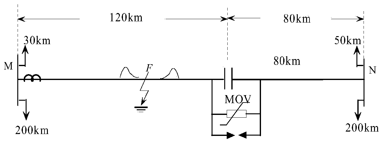
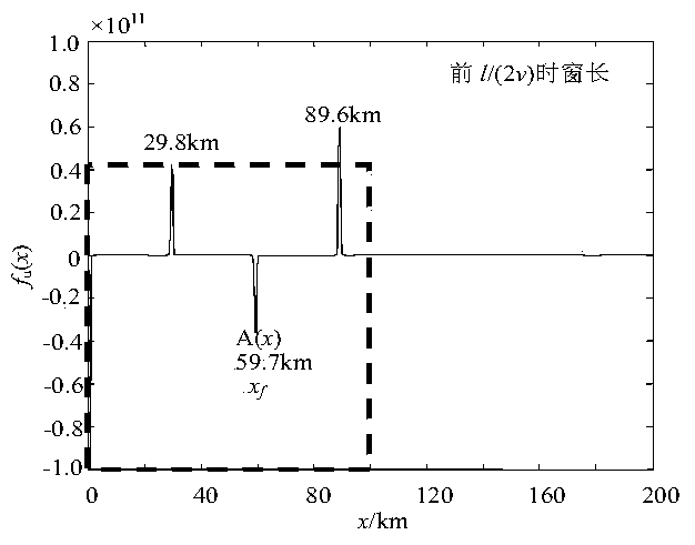
[0104] Embodiment 1: with figure 1 Taking the transmission line shown as an example, a ground fault occurs 60km away from terminal M on the left side of the TCSC element.
[0105] According to step 1 in the manual, the traveling wave data with a time window length of 1.5l / v is obtained at the measurement terminal (M terminal); according to step 2, the voltage traveling wave is constructed by using the current traveling wave and wave impedance of the adjacent healthy line to obtain u M = i k × Z c ;According to step 3, calculate the distribution u of the voltage traveling wave and current traveling wave along the line x,s (x,t) and i x,s (x,t); According to step 4, calculate the forward traveling wave and reverse traveling wave u + x,s and u - x,s ;According to step 5, calculate and extract the sudden change of forward traveling wave and reverse traveling wave with and energy with According to step 6, construct the ranging function. get ranging function f uI (x...
Embodiment 2
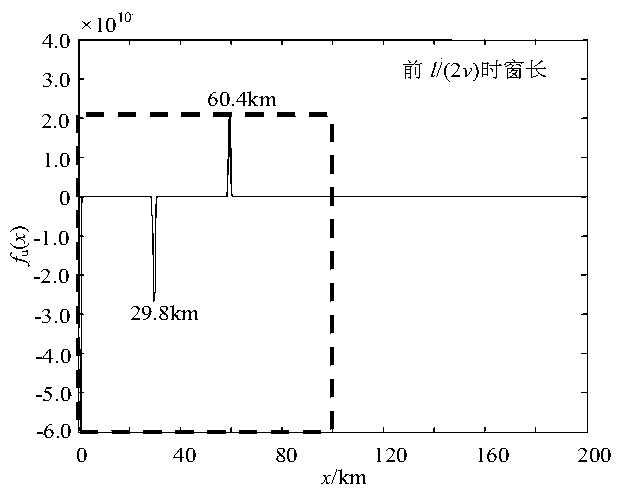
[0106] Embodiment 2: with figure 1 Taking the transmission line shown as an example, a ground fault occurs at a distance of 140km from the M terminal on the right side of the TCSC element.
[0107] According to step 1 in the manual, the traveling wave data with a time window length of 1.5l / v is obtained at the measurement terminal M; according to step 2, the voltage traveling wave is constructed by using the current traveling wave and wave impedance of the adjacent sound line to obtain u M = i k × Z c ;According to step 3, calculate the distribution u of the voltage traveling wave and current traveling wave along the line x,s (x,t) and i x,s (x,t); According to step 4, calculate the forward traveling wave and reverse traveling wave u + x,s and u - x,s ;According to step 5, calculate and extract the sudden change of forward traveling wave and reverse traveling wave with and energy with According to step 6, construct the ranging function. get ranging function f ...
PUM
 Abstract
Description
Claims
Application Information
 - R&D
- Intellectual Property
- Life Sciences
- Materials
- Tech Scout
- Unparalleled Data Quality
- Higher Quality Content
- 60% Fewer Hallucinations
Browse by: Latest US Patents, China's latest patents, Technical Efficacy Thesaurus, Application Domain, Technology Topic, Popular Technical Reports.
© 2025 PatSnap. All rights reserved.Legal|Privacy policy|Modern Slavery Act Transparency Statement|Sitemap|About US| Contact US: help@patsnap.com


