A kind of vivaldi antenna device applied to imaging system

An antenna device and imaging system technology, which is applied in the direction of antenna, antenna coupling, antenna components, etc., can solve the problems of excessive mutual coupling and narrow beam width, and achieve the effect of increasing beam width, simple processing, and wide beam characteristics

Active Publication Date: 2018-04-24
SOUTHEAST UNIV
View PDF4 Cites 0 Cited by
  • Summary
  • Abstract
  • Description
  • Claims
  • Application Information

AI Technical Summary

Problems solved by technology

[0003] Purpose of the invention: In order to solve the problem that the radiation beam width of the E-plane of the existing Vivaldi antenna is too narrow and the mutual coupling is too strong, the present invention provides a Vivaldi antenna device applied to the imaging system, which can be used without increasing the inherent size of the antenna and without destroying the H-plane Based on the radiation characteristics, the expansion of the beam width of the E-plane pattern is realized

Method used


Image

  • A kind of vivaldi antenna device applied to imaging system
  • A kind of vivaldi antenna device applied to imaging system
  • A kind of vivaldi antenna device applied to imaging system

Examples


Embodiment 1

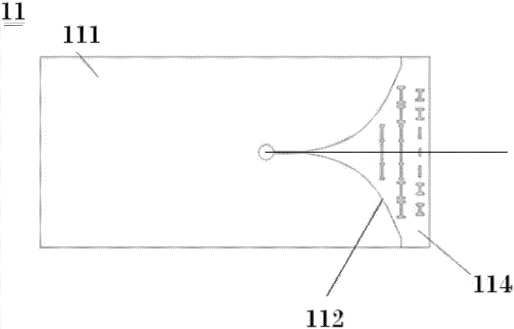
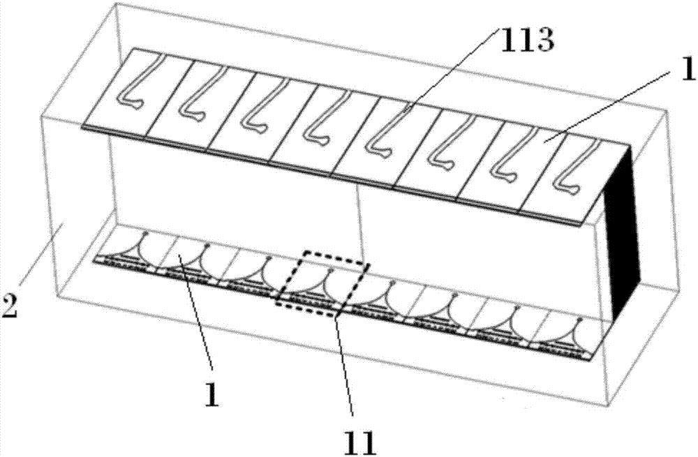
[0022] In a general imaging system, two sets of Vivaldi antenna arrays are respectively fixed on the upper and lower inner surfaces of the test system bracket, one of which is responsible for signal transmission, and the other is responsible for signal reception, and the two sets of antenna arrays are placed opposite to each other as the transceiver terminals of the system. Such as figure 1 As shown, in this embodiment, the Vivaldi antenna device applied to the imaging system includes: two sets of Vivaldi antenna arrays 1 and supports 2, the supports 2 are in a cubic structure, and two groups of Vivaldi antenna arrays 1 are respectively arranged in two opposite inner sides of the supports 2. On the surface, each Vivaldi antenna array 1 includes a plurality of Vivaldi antennas 11 arranged side by side, and the two sides of the antenna 11 are respectively called the front and the back, and the fronts of the two groups of Vivaldi antenna arrays 1 are arranged oppositely in the sup...

Embodiment 2

[0025] Such as Figure 6As shown, the Vivaldi antenna device applied to the imaging system in this embodiment also includes two sets of Vivaldi antenna arrays 1 and brackets 2. The difference from Embodiment 1 is that in this embodiment, in order to further reduce the crosstalk between systems, the antenna In terms of isolation, each group of Vivaldi antenna arrays 1 is also provided with a three-dimensional metamaterial lens 3, and the three-dimensional metamaterial lens 3 includes two groups of semi-rectangular metal outer frames 31 and multilayer metamaterial array dielectric inserts 32, two groups of the same size The metal frame 31 clamps the Vivaldi antenna array 1 therein, and is distributed symmetrically with respect to the Vivaldi antenna array 1, and each group of metal frames 31 on both sides of the Vivaldi antenna array 1 all isolates each Vivaldi antenna; The side is the front side, the metal frame 31 is connected to the support 2, and the boundary of the metal fr...


PUM


Abstract

The invention discloses a Vivaldi antenna device applied to an imaging system. A planar metamaterial lens is arranged at a port of a tapered slot line of an antenna by a novel artificial electromagnetic material, the wave beam width of H-surface directional diagram is expanded on the basis of no increase on a fixed size of the antenna and no damage to E-surface radiation characteristic, signal intercoupling among antennas is further isolated by loading a metal cavity, the wave beam widths of E-surface directional diagram and the H-surface direction diagram are expanded by loading a three-dimensional metamaterial lens, so that the demands of simultaneously improving isolation degree and the wave beam width are achieved. With the Vivaldi antenna device disclosed by the invention, the problems of excessive narrow E-surface radiation wave beam width and excessive high intercoupling of an existing Vivaldi antenna are solved, and the Vivaldi antenna device has the advantages of high isolation degree, wide wave beam width, low cost, light weight, small size and the like, is easy to process and is convenient to integrate.

Description

technical field [0001] The invention belongs to the field of antenna materials, in particular to a Vivaldi antenna device applied to an imaging system. Background technique [0002] New artificial electromagnetic materials, also known as metamaterials, are usually composed of periodic subwavelength metal or dielectric structures. According to the Lorentz model description, metamaterial structures can effectively couple electric or magnetic fields and provide electric or magnetic resonance properties. Since metamaterial elements are usually related to sub-wavelength dimensions, the equivalent medium theory is satisfied. Metamaterial arrays can utilize the complex equivalent dielectric constant c(ω)-c r (ω)+ic 1 (ω) and equivalent permeability μ(ω)=μ r (ω)+iμ 1 (ω) to describe it. A series of metamaterial lenses based on zero-refractive index, graded-refractive index, and transformation optics have been studied and reported. Since Gibson developed the Vivaldi antenna in...

Claims


Application Information

Patent Timeline
Patent Type & Authority Patents(China)
IPC IPC(8): H01Q1/38H01Q1/52H01Q19/06H01Q15/02H01Q13/02
CPCH01Q1/38H01Q1/52H01Q1/523H01Q13/02H01Q15/02H01Q19/06
Inventor 崔铁军潘柏操孙忠良
Owner SOUTHEAST UNIV
Why Eureka
Try Eureka