Electric power cabinet structure with ventilating pressure-reducing plate

A technology for power cabinets and ventilation panels, which is applied in the cooling/ventilation of substations/switchgears, substations/distribution equipment shells, etc., and can solve problems such as insufficient air convection, poor heat dissipation, and poor natural outflow effects. Achieve the effect of avoiding local high fever and cooling effect

Inactive Publication Date: 2016-07-06
WUXI XISHAN ANDA EXPLOSION PROOF ELECTRIC EQUIP
View PDF5 Cites 1 Cited by
  • Summary
  • Abstract
  • Description
  • Claims
  • Application Information

AI Technical Summary

Problems solved by technology

The problem of the traditional power cabinet is: the air convection inside and outside the cabinet is not sufficient, especially the natural outflow of the internal hot air is not good, and the heat dissipation effect is not good

Method used


Image

  • Electric power cabinet structure with ventilating pressure-reducing plate
  • Electric power cabinet structure with ventilating pressure-reducing plate

Examples


Embodiment Construction

[0011] The specific embodiments of the present invention will be further described below in conjunction with the accompanying drawings.

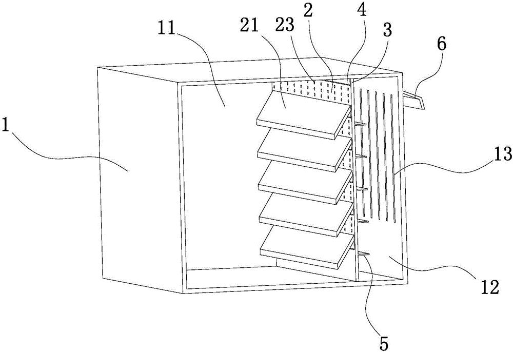
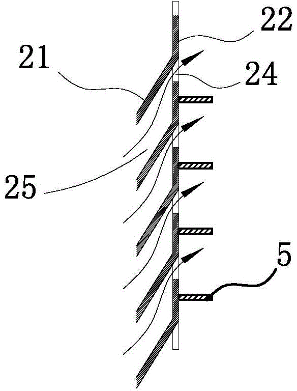
[0012] like figure 1 , figure 2 As shown, the structure of the power cabinet with ventilation and decompression plates in this embodiment includes a cabinet body 1 and a ventilation panel 2 inside the cabinet body 1, and the ventilation panel 2 divides the interior of the cabinet body 1 into an electrical device installation cavity 11 and a ventilation and heat dissipation cavity 12. The side wall of the ventilation and heat dissipation cavity 12 has a ventilation groove 13; the ventilation plate is fixedly connected with the cabinet body 1 by means of the frame body 3 on both sides, and the upper end of the ventilation plate 1 and the inner top surface of the cabinet body 1 have a ventilation top gap 4 The ventilation plate 2 includes an airflow introduction plate 21 and an airflow derivation plate 22, the introduction plate 21 is arrange...


PUM


Abstract

The invention relates to an electric power cabinet structure with a ventilating pressure-reducing plate. The structure comprises a cabinet body and a ventilating plate in the cabinet body. The ventilating plate separates the inside of the cabinet body into an electrical device installation cavity and a ventilating heat dissipation cavity, and the side wall of the ventilating heat dissipation cavity is provided with ventilating slots; the ventilating plate is fixedly connected with the cabinet body by means of a frame body at the two sides, and the upper end of the ventilating plate and the inner top surface of the cabinet body are provided with ventilating top gaps; the ventilating plate comprises air-flow lead-in plates and air-flow lead-out plates, the air-flow lead-in plates are aslant arranged downwards relative to the frame body, the lead-out plates are parallel to the surface of the frame body, lead-in grooves are arranged between the lead-in plates adjacent to each other at upper positions and lower positions, and lead-out grooves are arranged between adjacent lead-out plates; the lead-out plates are also uniformly provided with ventilating holes; the lead-out plates in the ventilating heat dissipation cavity are connected with flow guide plates, and the end portions of the flow guide plates maintain convection gaps with the side wall, which is provided with the ventilating grooves, of the cabinet body; and a shielding plate fixedly connected with the outer wall of the cabinet body is arranged at the upper potions of the ventilating grooves, and the end portion of the shielding plate is inclined towards the bottom surface of the cabinet body.

Description

Technical field: [0001] The invention relates to the field of explosion-proof electrical technology, in particular to a ventilation structure of an electric cabinet. Background technique: [0002] At present, most of the power transmission and transformation facilities installed outdoors in the power system adopt a box-type structure, that is, a power box or a power cabinet. The cabinet body of the power cabinet is generally provided with a heat insulation layer to prevent sun exposure, and an air duct is provided inside, and a ventilation plate is provided at the vent of the air duct to prevent safety problems caused by untimely heat dissipation of the power facilities. The problem of the traditional power cabinet is that the air convection inside and outside the cabinet is not sufficient, especially the natural outflow of the internal hot air is not good, and the heat dissipation effect is not good. Invention content: [0003] In view of the above-mentioned shortcomings...

Claims


Application Information

Patent Timeline
Patent Type & Authority Applications(China)
IPC IPC(8): H02B1/56H02B1/28
Inventor 尤建东
Owner WUXI XISHAN ANDA EXPLOSION PROOF ELECTRIC EQUIP
Why Eureka
Try Eureka