
Mobile terminal

A mobile terminal, touch panel technology, applied in the direction of telephone structure, telephone communication, instruments, etc., can solve the problem of reducing the detection distance of the optical distance sensor chip 10, reducing the intensity of received external light, and reducing the accuracy of light and distance detection. And other issues

Active Publication Date: 2016-07-06
QINGDAO HISENSE MOBILE COMM TECH CO LTD
View PDF4 Cites 6 Cited by
  • Summary
  • Abstract
  • Description
  • Claims
  • Application Information

AI Technical Summary

Problems solved by technology

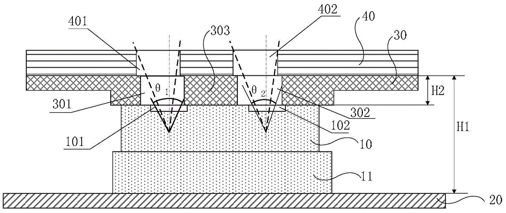
However, due to the installation tolerance and the appearance tolerance of the PCB 20 itself in the process of installing the black rubber sleeve 30 and the optical distance sensor chip 10, the superposition of the above tolerances will lead to the position of the left through hole 301 and the right through hole 302 on the black rubber sleeve 30. Alignment deviation occurs with the positions of the transmitting hole 101 and the receiving hole 102 of the optical distance sensing chip 10, or the positions of the left through hole 301 and the right through hole 302 on the black rubber sleeve 30 are respectively in line with the positions of the first through hole 302 on the touch screen panel 40. There is an alignment deviation between the first through hole 401 and the second through hole 402, so that the original emission angle θ of the light distance sensor chip 10 1 and the original receiving angle θ 2 has been reduced (the reduced angle is as figure 1 shown by the dotted line in ), which in turn leads to a reduction in the detection distance of the optical distance sensor chip 10, a reduction in the intensity of received external light, and a reduction in the accuracy of light and distance detection

Method used


Image

  • Mobile terminal
  • Mobile terminal
  • Mobile terminal

Examples


Embodiment Construction

[0021] The following will clearly and completely describe the technical solutions in the embodiments of the present invention with reference to the accompanying drawings in the embodiments of the present invention. Obviously, the described embodiments are only some, not all, embodiments of the present invention. Based on the embodiments of the present invention, all other embodiments obtained by persons of ordinary skill in the art without making creative efforts belong to the protection scope of the present invention.

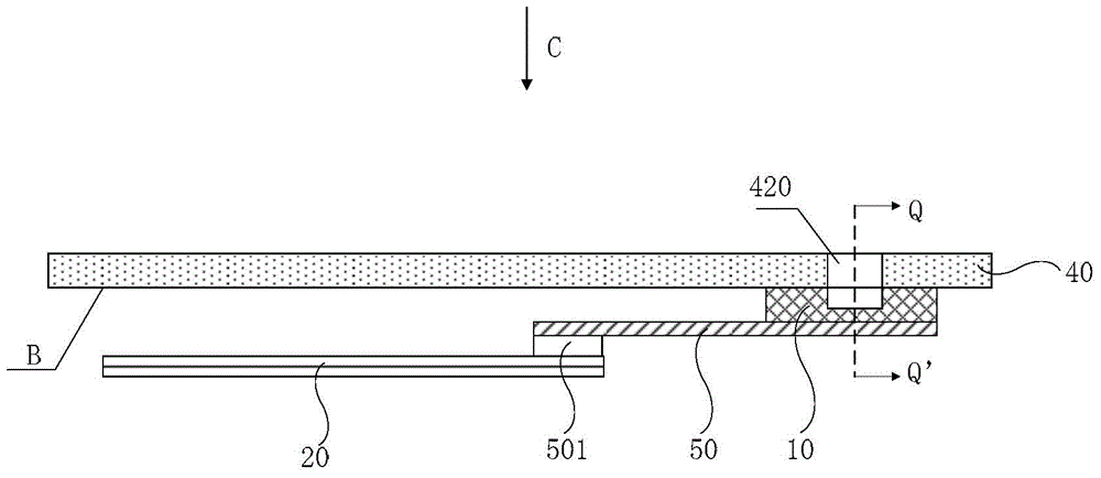
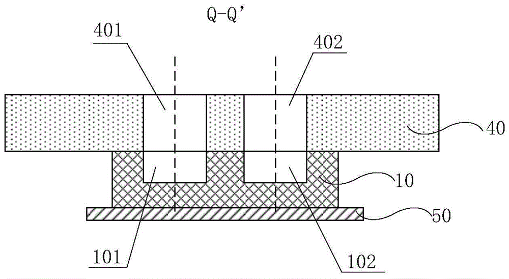
[0022] An embodiment of the present invention provides a mobile terminal, such as figure 2 As shown, a touch panel 40 and a printed circuit board 20 (PCB) are included. In addition, the mobile terminal also includes a flexible circuit board 50 (full English name: Flexible Printed Circuit Board, English abbreviation: FPC), and an optical distance sensor chip 10 fixed on the side B of the touch panel 40 opposite to the printed circuit board 20 .

[0023] In ad...


PUM


Abstract

The embodiment of the invention provides a mobile terminal, which relates to the field of manufacturing of mobile terminals, and can reduce the probability of influence of contour tolerance and installation tolerance of a component during an installation process on the transmitting angle of a transmitting hole and the receiving angle of a receiving hole in an optical distance sensing chip. The mobile terminal comprises a touch panel and a printed circuit board, and further comprises a flexible circuit board, and an optical distance sensing chip fixed on one side of the touch panel facing the printed circuit board. The optical distance sensing chip is provided with a transmitting hole and a receiving hole, and the touch panel is provided with light-permeable structures at the positions corresponding to the transmitting hole and the receiving hole. The optical distance sensing chip is connected with the printed circuit board via the flexible circuit board.

Description

technical field [0001] The invention relates to the field of mobile terminal production, in particular to a mobile terminal. Background technique [0002] At present, mobile terminals such as mobile phones and handheld computers have become one of the necessities of people's daily life. The user experience of mobile terminals has also attracted more and more attention. In order to enhance user experience, different types of sensors, such as thermal sensor chips, gravity sensor chips, optical distance sensor chips, etc., are generally installed in mobile terminals. Wherein, a mobile terminal such as a mobile phone is provided with an optical distance sensing chip, and the optical distance sensing chip includes a light sensing component and a distance sensing component. On the one hand, the light sensing component can detect the ambient light to adjust the backlight of the display screen in the mobile terminal to adapt to the ambient light; on the other hand, the distance se...

Claims


Application Information

Patent Timeline
IPC IPC(8): H04M1/02G06F3/041
CPCG06F3/041H04M1/026
Inventor 张倩倩王富敏王建磊
Owner QINGDAO HISENSE MOBILE COMM TECH CO LTD
Learn More