Method and system for controlling the speed of a vehicle

A vehicle and speed technology, applied in the field of controlling vehicle speed

Active Publication Date: 2016-07-06
RENAULT SA
View PDF13 Cites 6 Cited by
  • Summary
  • Abstract
  • Description
  • Claims
  • Application Information

AI Technical Summary

Problems solved by technology

[0011] However, the main disadvantage that this system has is that although it makes it possible to keep the speed of the vehicle at the speed limit when the vehicle is already traveling in this zone, it is impossible to avoi

Method used


Image

  • Method and system for controlling the speed of a vehicle
  • Method and system for controlling the speed of a vehicle
  • Method and system for controlling the speed of a vehicle

Examples


Embodiment Construction

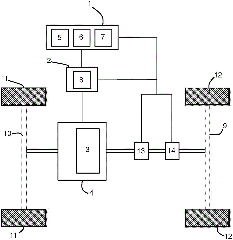
[0050] figure 1 One embodiment of the system for controlling the speed of a vehicle is shown. This vehicle may be a motor vehicle of hybrid or electric type or even a motorcycle.

[0051] The vehicle is equipped with a drive train 4 comprising at least one electric machine 3 and associated storage elements, in particular a battery.

[0052] As already stated, the vehicle may be a strictly electric vehicle or a hybrid vehicle comprising a heat engine associated with at least one electric machine 3 .

[0053] The vehicle also comprises a rear end 9 and a front end 10 each comprising two wheels 11 , 12 . One or even both of these two ends 9 , 10 can be coupled to the shaft of the rotor of the electric machine 3 differently depending on whether the vehicle has two drive wheels 11 , 12 or four drive wheels.

[0054] The vehicle in which the shaft of the rotor is coupled to the electric machine 3 at one or both ends 9, 10 comprises drive wheels 11, 12 and the storage element form...


PUM


Abstract

The invention relates to a method and system for controlling the speed (V1) of a vehicle, in particular of an electric or hybrid vehicle capable of travelling on a roadway, said method including the following steps: estimating (15) the location of the vehicle on the roadway; predicting (16), in accordance with the location of the vehicle, a roadway zone (B) comprising a speed limit (V2) that said vehicle is likely to travel through; and determining a control current (I) of an energy-recovery device enabling the vehicle to reach said speed limit (V2) upon entering said zone (B) when the speed (V1) of the vehicle is higher than said speed limit (V2).

Description

technical field [0001] The invention relates to a method for controlling the speed of a vehicle and a system for implementing the method. [0002] The invention also relates to a vehicle, in particular an electric vehicle or a hybrid vehicle, comprising such a speed control system. Background technique [0003] Conventionally, a lane includes a plurality of zones, each of which has a different speed limit than the preceding zone. [0004] This speed limit must be observed by those vehicles passing through the zone affected by this limit. [0005] Therefore, when the vehicle reaches the vicinity of such a zone, the driver is generally alerted by a signaling panel which informs him to observe this speed limit. [0006] The driver then acts on the vehicle to adjust its speed to the speed limit. [0007] For this reason, when, for example, it is the right time to slow down the vehicle in order to reach the speed limit, the driver usually takes his foot off the accelerator a f...

Claims


Application Information

Patent Timeline
IPC IPC(8): B60W30/14B60W30/18B60W20/14
CPCB60W30/143B60W30/146B60W30/18127B60W2050/0011B60W2520/10B60W2520/105B60W2710/083B60W2720/10B60W2720/103B60W2720/106B60W20/14B60W2552/20B60W2555/60B60W2556/50
Inventor F·里森梅伊O·比斯巴特
Owner RENAULT SA
Why Eureka
Try Eureka