Switching device and switch-off method for operating a switching device

A switching device, operating switch technology, applied in the direction of automatic disconnection emergency protection devices, electrical switches, circuit devices, etc., can solve problems such as high cost, achieve compressive strength, prevent reflow, and improve compressive strength. Effect

Active Publication Date: 2016-07-06
SIEMENS ENERGY GLOBAL GMBH CO & KG
View PDF5 Cites 0 Cited by
  • Summary
  • Abstract
  • Description
  • Claims
  • Application Information

AI Technical Summary

Problems solved by technology

This requires high-cost unconventional switch positions, so that the unconventional switch positions determine a large part of the cost of the switchgear

Method used


Image

  • Switching device and switch-off method for operating a switching device
  • Switching device and switch-off method for operating a switching device
  • Switching device and switch-off method for operating a switching device

Examples


Embodiment Construction

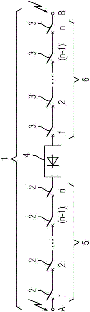
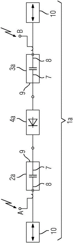
[0031] figure 1 The circuit diagram of shows a switching device 1 for interrupting a current path between points A and B. The electrical switching device 1 is preferably designed for switching a direct current driven by a direct voltage. The electrical switching device 1 has a first conventional switching position 2 and a second conventional switching position 3 . Furthermore, the switching device 1 has an unconventional switching position 4 . The non-conventional switch position 4 is arranged electrically in series between the first conventional switch position 2 and the second conventional switch position 3 . In this case, n first normal switching positions 2 and n second normal switching positions 3 are provided. For example, ten first normal switching positions 2 and ten second normal switching positions 3 can be provided. The first normal switching positions 2 are all electrically connected in series, wherein the first normal switching positions 2 on one side of the n...


PUM


Abstract

The invention relates to a switching device (1, 1a) comprising a first conventional switching point (2, 2a) and a second conventional switching point (3, 3a) which are electrically connected in series via a non-conventional switching point (4, 4a).

Description

technical field [0001] The invention relates to a switching device having a first normal switching position, a second normal switching position and an unconventional switching position. Background technique [0002] Such a switching device is known, for example, from document DE 10 2011 005 905 A1. There, a switching device is described which has gas-insulated circuit breakers and vacuum circuit breakers as conventional switching points. Electrically connected in parallel to the vacuum circuit breaker is a device for generating a reverse current, which has a thyristor. The device for generating the reverse current is designed with unconventional switching positions. [0003] The known switching devices are especially suitable for switching direct currents. In order to interrupt the direct current, a reverse current is applied to the direct current to be interrupted by means of the device for generating a reverse current in order to interrupt the direct current. [0004] ...

Claims


Application Information

Patent Timeline
IPC IPC(8): H01H33/59H01H89/00H02J1/00H02H3/00H01H9/54
CPCH01H9/548H01H33/596H01H89/00H01H9/54H01H33/66
Inventor L-R.贾尼克
Owner SIEMENS ENERGY GLOBAL GMBH CO & KG
Why Eureka
Try Eureka