

Toy launcher
A transmitter and toy technology, applied in sports accessories, animal taming devices, animal husbandry, etc., can solve the problems of easy fatigue and reduce pet interest in playing, and achieve the effects of simple structure, improved interest in play, and convenient use
- Summary
- Abstract
- Description
- Claims
- Application Information
AI Technical Summary
Problems solved by technology
Method used
Image

Examples
Embodiment 1
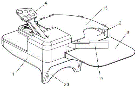
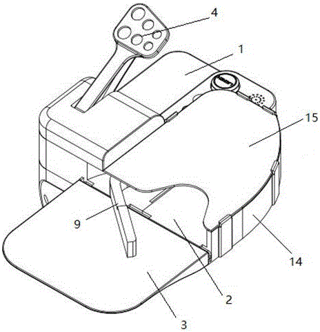
[0027] Such as Figure 1-4 The shown toy launcher includes a shell 1 and a projected body, and also includes a foot pedal 4, a transmission device and a striking rod 9 that are sequentially connected by transmission. The shell 1 is equipped with a side support plate that is easy to disassemble. 2 and the front supporting plate 3, the side supporting plate 2 and the front supporting plate 3 form a launching track. The striking rod 9 rotates in the launching track, and exerts a force on the projected object, thereby launching the projected object on the launching track.
[0028] The transmission device is located in the housing 1 and includes a first rotating shaft 6, a first rotating gear 7, a second rotating gear 10 and a second rotating shaft 8. One end of the pedal 4 stretches out of the housing 1, and the other One end is sleeved on the first rotating shaft 6, the first rotating gear 7 is fixed on the first rotating shaft 6 and meshed with the second rotating gear 10 fixed...
Embodiment 2
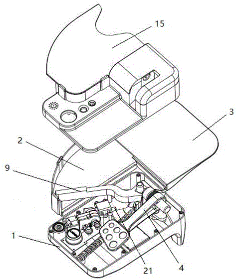
[0038]On the basis of embodiment 1, we can also use the remote control system to remotely control the launch toy, and also include the remote control system, the remote control system includes a controller 12.1, a driver 12.3, a servo motor 12.4, a receiver 12.5 for receiving remote control signals, and a The remote control signal is transmitted to the transmitter of the receiver, the extension spring 11, the positioning clip 10 and the locking swing lever 21 that blocks the movement of the positioning clip 10;
[0039] Described controller 12.1, driver 12.3, servomotor 12.4 and receiver 12.5 are arranged in control box 12; Described receiver 12.5 and driver 12.3 are connected with controller 12.1 respectively, and described driver 12.3 drives servomotor 12.4, and servomotor 12.4 It is linked with the locking swing rod 19; one end of the tension spring 11 is fixed on the ball hitting member 9, and the other end is fixed on one side inside the housing 1.
[0040] It also includ...
PUM
| Property | Measurement | Unit |
|---|---|---|
| Length | aaaaa | aaaaa |
| Width | aaaaa | aaaaa |
Abstract
Description
Claims
Application Information