A method of improving casing rigidity

A technology of rigidity and width, applied in the field of improving the rigidity of the casing, can solve the problems of restricting the strengthening function, etc., and achieve the effects of improving the vibration characteristics, increasing the rigidity, and improving the coaxiality of the whole machine

Active Publication Date: 2017-12-22
AECC SHENYANG ENGINE RES INST
View PDF4 Cites 0 Cited by
  • Summary
  • Abstract
  • Description
  • Claims
  • Application Information

AI Technical Summary

Problems solved by technology

The method of multiple ring ribs improves the rigidity of the casing to a certain extent, but its too simple structure limits the further improvement of its reinforcement function

Method used


Image

  • A method of improving casing rigidity
  • A method of improving casing rigidity
  • A method of improving casing rigidity

Examples


Embodiment 1

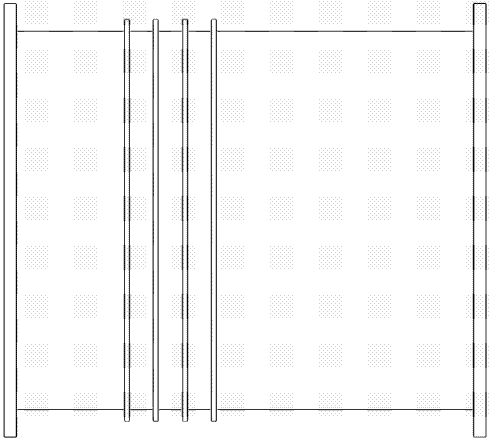
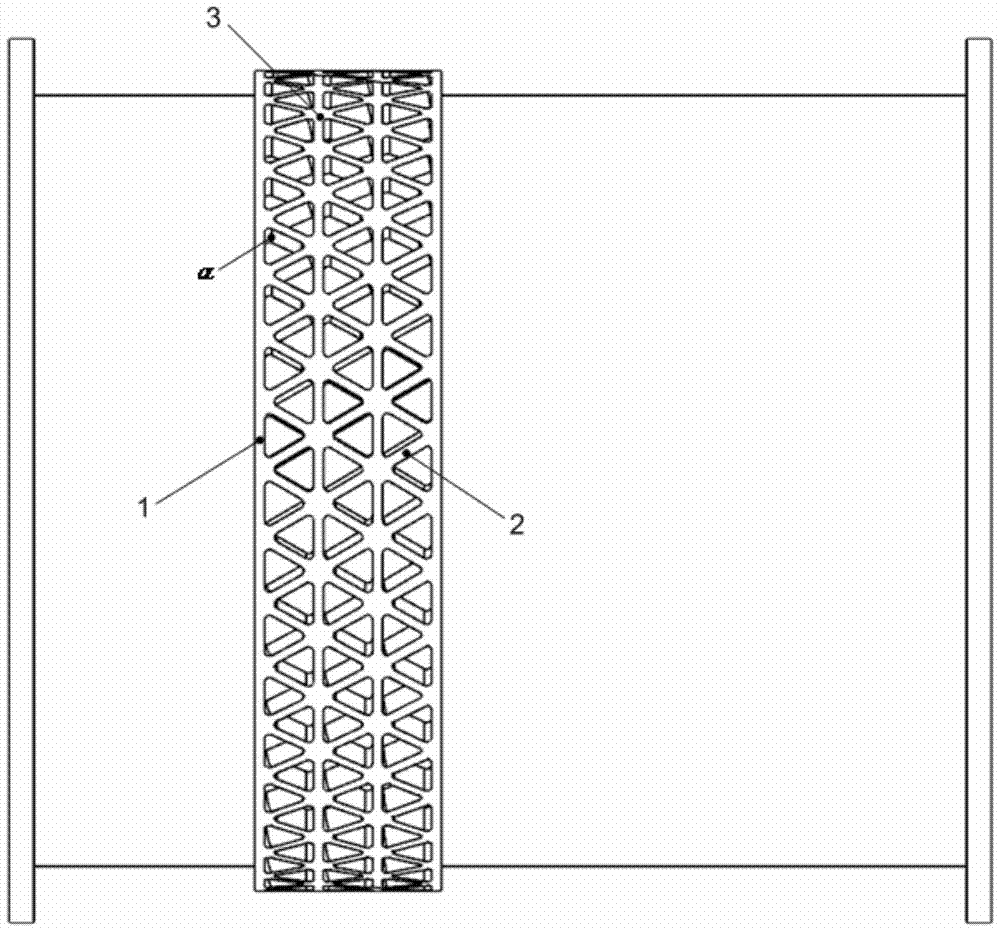
[0038] The invention provides a method for improving the rigidity of the casing, which is characterized in that: the method for improving the rigidity of the casing adopts an annular reinforcement rib 1, a spiral reinforcement rib 2, an equal grid reinforcement rib structure 3, a reinforcement area 4 and The combined structure of casing 5. According to the known shell radius R of the reinforced area, the corresponding design elements are determined according to Formula 1 within the initial width of the reinforced area, and then through the strength calculation and verification, four design elements are accurately selected to complete the casing with equal grid reinforcement Rigid design.

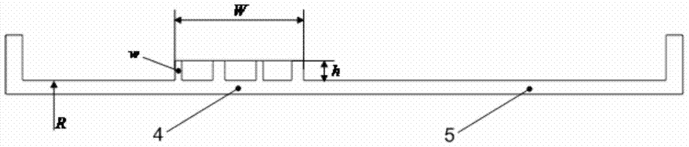
[0039] The reinforced area 4 with a width of W is a conical segment, and this method is applied to the conic surface projection;

[0040] The annular ribs 1 are equidistantly distributed along the engine axis in the reinforced area 4 with a width W.

[0041] A stable triangular reinforcing...

Embodiment 2

[0065]This embodiment provides a method for improving the rigidity of the casing, which is characterized in that: the method for improving the rigidity of the casing adopts ring ribs 1, spiral ribs 2, grid rib structures 3, and reinforced areas 4 Combined structure with casing 5. According to the known shell radius R of the reinforced area, the corresponding design elements are determined according to Formula 1 within the initial width of the reinforced area, and then through the strength calculation and verification, four design elements are accurately selected to complete the casing with equal grid reinforcement Rigid design.

[0066] The reinforced area 4 with a width W is a cylindrical segment;

[0067] The annular ribs 1 are equidistantly distributed along the engine axis in the reinforced area 4 with a width W.

[0068] A stable triangular reinforcing structure is formed between two adjacent annular reinforcing ribs 1 by a spiral reinforcing rib 2, the triangle must be...


PUM


Abstract

A method for improving the rigidity of the case adopts a combined structure of ring ribs, spiral ribs, and grid rib structures, a reinforced area, and the case. According to the known shell radius R of the reinforcement area, the corresponding design elements are determined according to the formula within the initial width of the reinforcement area, and then through the strength calculation and verification, four design elements are accurately selected to complete the grid reinforcement ribs to improve the rigidity of the casing The reinforced area with a width of W is a cylindrical segment or a conical segment; the annular ribs are equidistantly distributed along the engine axis in the reinforced area with a width of W; the spiral ribs between two adjacent annular ribs form a stable The triangular reinforcement structure; the starting point, end point and intersection point of the spiral reinforcement are all on the ring reinforcement. The invention has the advantages of better improving the ability of the casing to bear various loads and containing rotor blades, improving the structural efficiency of the ribs, significantly increasing the rigidity of the casing, and being beneficial to improving the coaxiality of the whole machine and improving the vibration characteristics.

Description

technical field [0001] The invention relates to the field of aero-engines, in particular to a method for improving the rigidity of the casing. Background technique [0002] The aero-engine casing is a typical rotary cylindrical structure, its function is to form a stable working flow path of the engine, fix a series of structural parts such as internal stator blades and external accessories, and at the same time as the main structure of the engine, it needs to transmit engine thrust and bear Various loads and maneuvering overloads, including the rotor blades, its structural strength will also directly affect the coaxiality of the engine and the vibration characteristics of the whole machine, so how to reasonably increase the rigidity of the casing will be directly related to the realization of the above functions. The structural performance of the engine has an important influence. [0003] Traditional structures such as figure 1 As shown in Fig. 1, the engine casing parti...

Claims


Application Information

Patent Timeline
Patent Type & Authority Patents(China)
IPC IPC(8): F01D25/24
Inventor 李健吕春光刘宇
Owner AECC SHENYANG ENGINE RES INST
Why Eureka
Try Eureka