Petroleum pipeline bracket device

A technology for oil pipelines and support devices, which is applied in the direction of pipeline supports, pipes/pipe joints/fittings, mechanical equipment, etc., which can solve the problems of inconvenient pipeline erection and installation, broken oil pipeline supports, oil pipeline supports without lifting and lateral adjustment functions, etc. problems, to prevent breakage and ensure smooth flow

Inactive Publication Date: 2016-07-13
SICHUAN XINGZHI ZHIHUI INTPROP OPERATION CO LTD
View PDF8 Cites 10 Cited by
  • Summary
  • Abstract
  • Description
  • Claims
  • Application Information

AI Technical Summary

Problems solved by technology

[0003] The purpose of the present invention is to overcome the deficiencies of the prior art and provide a petroleum pipeline support device to solve the problem that the petroleum pipeline support does not have the functions of lifting and lateral adjustment, and it is not convenient to use pipeline erection and installation. When the oil pipeline will change with the temperature Expansion with heat and contraction with cold can easily cause rupture of oil pipelines or brackets

Method used


Image

  • Petroleum pipeline bracket device
  • Petroleum pipeline bracket device
  • Petroleum pipeline bracket device

Examples


Embodiment 1

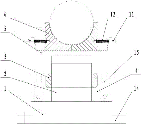
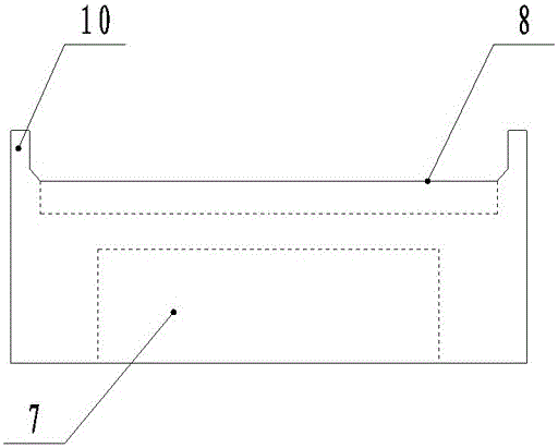
[0020] Such as Figure 1-3 As shown, a kind of petroleum pipeline support device of the present invention comprises pipeline support base 1, lift screw rod 2, lift nut 3, support seat 5 and pipeline stop block 6, and lift screw rod 2 is arranged on pipeline support base 1 to oil The pipe bracket acts as a general support, the lifting nut 3 is threaded and sleeved on the lifting screw 2, the lower end of the support seat 5 is provided with a supporting groove 7, and the supporting groove 7 is also set on the lifting screw 2, and the lifting nut 3 is lifted and lowered by rotating the lifting nut 3. The support seat 5; the upper end of the support seat 5 is provided with the installation chute 8 of the pipe limit block 6, and the two pipe stop blocks 6 are symmetrically arranged in the chute 8; the pipe support base 1 and the support seat 5 are arranged There is a jack installation port 4.

[0021] During use, the bottom of the pipeline support base 1 is provided with a bolt fi...

Embodiment 2

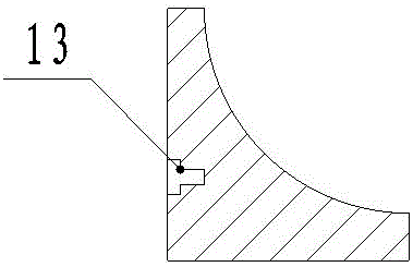
[0023] Such as image 3 As shown, an oil pipeline support device of the present invention, on the basis of Embodiment 1, limit block adjustment platforms 10 are arranged on both sides of the support seat 5, and horizontal screw holes are arranged on the limit block adjustment platform 10, and the screw holes are provided with limited Position block adjustment column 11, limit block adjustment column 11 can spirally rotate in the screw hole, and a nut clamped by a handle is also arranged at the outer end of limit block adjustment column 11, and limit block adjustment column 11 adjusts the pipeline limit Block 6 moves in chute 8 . A buffer spring 12 is sheathed on the limit block adjusting column 11 , and both ends of the buffer spring 12 are squeezed on the limit block adjusting table 10 and the pipeline limit block 6 respectively. A T-shaped hole 13 is arranged on the pipe limit block 6 corresponding to the limit block adjustment column 11, the buffer spring 12 is squeezed in...


PUM


Abstract

The invention discloses a petroleum pipeline bracket device. The petroleum pipeline bracket device comprises a pipeline bracket base, a lifting screw rod, a lifting nut, a supporting seat and pipeline limiting blocks, wherein the lifting screw rod is arranged on the pipeline bracket base and is used for totally supporting a petroleum pipeline bracket; the lifting nut sleeves the lifting screw rod in a threaded connection manner; a supporting groove is formed in the lower end of the supporting seat, and also sleeves the lifting screw rod; the supporting seat is lifted by rotating the lifting nut; mounting sliding grooves of the pipeline limiting blocks are formed in the upper end of the supporting seat; the two pipeline limiting blocks are symmetrically arranged in the sliding grooves; a jack mounting opening is formed between the pipeline bracket base and the supporting seat. According to the petroleum pipeline bracket device disclosed by the invention, the petroleum pipeline bracket is regulated in the transverse direction and the longitudinal direction, so that the situation that the petroleum transporting pipeline or the bracket is broken by thermal expansion and contraction of the petroleum transporting pipeline can be effectively avoided, and the smoothness of the petroleum transporting pipeline is guaranteed.

Description

technical field [0001] The invention relates to the field of oil pipeline supports, in particular to an oil pipeline support device. Background technique [0002] The oil pipeline is composed of oil pipes and their accessories. According to the needs of the process, it is equipped with corresponding oil pump units. It is designed and installed as a complete pipeline system to complete the tasks of oil loading, unloading and transportation. Common pipeline layout forms There are the following types: single-pipe system, double-pipe system, independent pipeline system, and the laying of oil pipelines. In order to reduce resistance, generally straight line laying methods are used as much as possible. There are three methods: ground, pipe trench and underground. The pipelines should be laid on the ground. The pipelines that have been buried in the ground or the pipelines that have been laid in the pipe trench should be gradually changed to the ground laying as much as possible in...

Claims


Application Information

Patent Timeline
Patent Type & Authority Applications(China)
IPC IPC(8): F16L3/02
CPCF16L3/02
Inventor 贺昶明
Owner SICHUAN XINGZHI ZHIHUI INTPROP OPERATION CO LTD
Why Eureka
Try Eureka