A multi-viewpoint three-dimensional display system and method
A three-dimensional display and multi-viewpoint technology, applied in instruments, stereo photography, optics, etc., can solve problems such as limited viewpoints and limited spatial resolution, achieve smooth moving parallax, and realize the effect of super multi-view display
- Summary
- Abstract
- Description
- Claims
- Application Information
AI Technical Summary
Problems solved by technology
Method used
Image
Examples
Embodiment 1
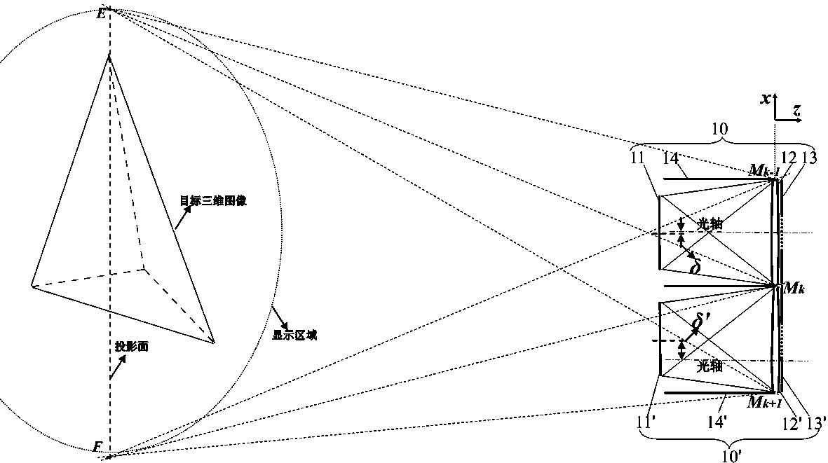
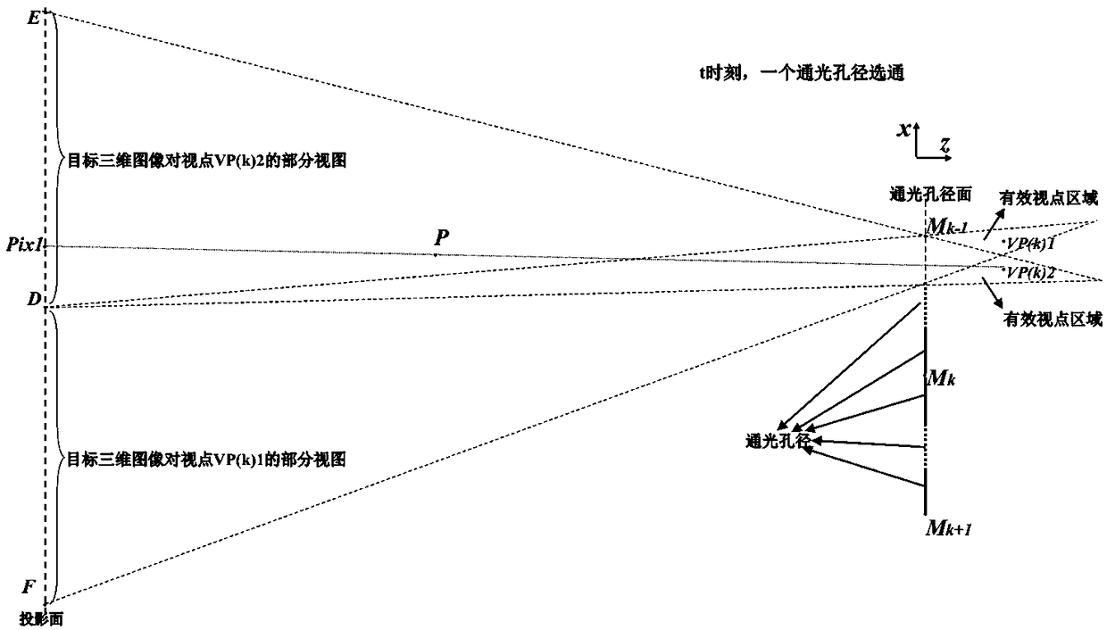
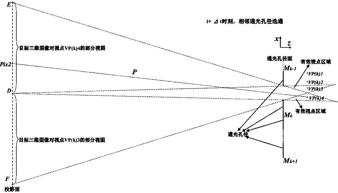
[0061] The optical path diagram of the first scheme of a multi-viewpoint three-dimensional display system based on the I-type time division multiplexing projection unit of the present invention is as follows figure 1 As shown, the I-type time-division multiplexing projection units are arranged in a plane, including a control unit and a number of I-type time-division multiplexing projection units 10, all the I-type time-division multiplexing projection units 10 are arranged adjacent to each other in a plane; The multiplexing projection unit 10 includes a display screen 11, a projection lens 12, and a clear aperture array 13; the display screen 11 is used to display optical image information; the projection lens 12 is used to project the image of the display screen 11 onto the projection surface; the clear aperture The array 13 is composed of a plurality of clear apertures and is placed at the aperture of the projection lens 12; the control unit is electrically connected to the dis...
Embodiment 2
[0082] The optical path diagram of the first scheme of a multi-viewpoint three-dimensional display system constructed based on a type II time division multiplexing projection unit of the present invention is as follows Figure 7 As shown, the type II time-division multiplexing projection unit is arranged in a plane. The difference from the first solution of embodiment 1 is that the time-division multiplexing projection unit 10 is a type-II time-division multiplexing projection unit. The distance between the display screen 11 and the projection lens 12 is equal to the focal length of the projection lens 12; the type II time-division multiplexing projection unit 10 also includes an auxiliary lens 20, a field lens 30, and a diffusion sheet 40 attached to the field lens 30. It is used to scatter incident light; the auxiliary lens 20 images the display screen 11 on the projection surface; the center of the field lens 30 is set on the projection surface and is used to image the project...
Embodiment 3
[0097] The optical path diagram of the first scheme of a multi-viewpoint three-dimensional display system constructed based on a type III time division multiplexing projection unit of the present invention is as follows Picture 9 As shown, the type III time division multiplexing projection unit is arranged in a plane, and the difference from the first solution of the embodiment 1 is that the time division multiplexing projection unit 10 is a type III time division multiplexing projection unit, which The distance between the display screen 11 and the projection lens 12 is greater than the focal length of the projection lens 12. The display screen 11 is projected by the projection lens 12 into a real image on the projection surface; the III time division multiplexing projection unit 10 also includes a field lens 30 and attached to the field lens 30 The diffusion sheet 40 is placed. The diffusion sheet 40 is used to diffuse the incident light. The center of the field lens 30 is set...
PUM
 Abstract
Description
Claims
Application Information
 - R&D
- Intellectual Property
- Life Sciences
- Materials
- Tech Scout
- Unparalleled Data Quality
- Higher Quality Content
- 60% Fewer Hallucinations
Browse by: Latest US Patents, China's latest patents, Technical Efficacy Thesaurus, Application Domain, Technology Topic, Popular Technical Reports.
© 2025 PatSnap. All rights reserved.Legal|Privacy policy|Modern Slavery Act Transparency Statement|Sitemap|About US| Contact US: help@patsnap.com


