
Inclinometry monitoring device and method for coupling optical positioning and real-time updating

A real-time update, optical positioning technology, applied in image data processing, 3D modeling, instruments, etc., can solve the problems of inability to truly reflect the overall deformation of the inclinometer tube, high instrument and labor costs, and low measurement accuracy. It is convenient to monitor the horizontal displacement of the foundation pit, the supporting cost is reduced, and the data is accurate and reliable.

Pending Publication Date: 2022-04-12
SOUTHEAST UNIV
View PDF0 Cites 0 Cited by
  • Summary
  • Abstract
  • Description
  • Claims
  • Application Information

AI Technical Summary

Problems solved by technology

According to the requirements of the specification, the portable inclinometer manually pulls the inclinometer probe and measures once every 500mm. The measuring points are discontinuous, the measurement accuracy is low, and it cannot truly reflect the overall deformation of the inclinometer pipe. The cost of equipment and labor is high, which has the disadvantages. Certain technical application limitations

Method used


Image

  • Inclinometry monitoring device and method for coupling optical positioning and real-time updating
  • Inclinometry monitoring device and method for coupling optical positioning and real-time updating
  • Inclinometry monitoring device and method for coupling optical positioning and real-time updating

Examples


Embodiment Construction

[0084] In order to make the purpose and technical advantages of the present invention clearer, the present invention will be further described in detail below. It should be understood that the specific embodiments described here are only used to explain the present invention, and are not intended to limit the scope of the present invention.

[0085] Those who do not indicate specific conditions in the embodiments are carried out according to conventional conditions; the instruments used are not indicated by manufacturers, and all can be obtained by commercially available conventional products; all technical terms used are consistent with those of those skilled in the art of the present invention Commonly understood to mean the same. The above is only for better description of specific embodiments, not intended to limit the present invention.

[0086] An inclinometer monitoring device and method for coupling optical positioning and real-time update, as shown in the schematic d...


PUM


Abstract

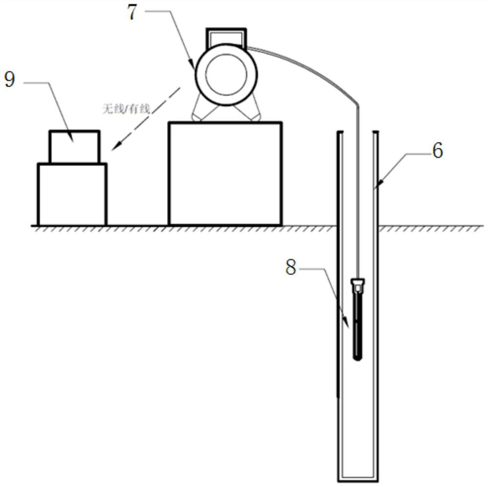
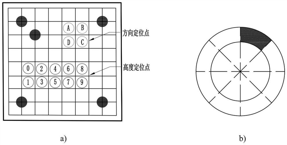
The invention discloses an inclinometer monitoring device and method coupling optical positioning and real-time updating, the inclinometer monitoring device comprises an inclinometer pipe, a lifting end, a probe end and a control end, specially designed feature points are arranged on the inner wall of the inclinometer pipe to improve the precision, and decoding positioning is facilitated; the lifting end controls the speed below the probe through an automatic program; the probe end is provided with a special lens and supporting facilities and is used for acquiring inclinometer tube image sequence information and transmitting data to the control end; and the control end carries out algorithm operation based on an optical positioning and tracking technology to obtain a three-position deformation model of the inclinometer pipe and a traditional inclinometer monitoring curve. According to the invention, the deformation of the inclinometer can be monitored more accurately, and emerging guarantee is provided for the safety and stability of engineering.

Description

Technical field: [0001] The invention relates to the technical field of geological disaster monitoring, and belongs to an inclinometer pipe deformation monitoring device, in particular to an inclinometer monitoring device and method coupled with optical positioning and real-time update. Background technique: [0002] With the acceleration of urbanization, the development of urban underground space has entered a stage of rapid development. As an important component of the development process, foundation pit engineering will lead to major hazards such as building damage, instability, and even casualties within the affected area. Therefore, the construction principle of "safety first" must be implemented. In foundation pit engineering, the degree of horizontal displacement of the foundation pit is the most important factor affecting the safety of the foundation pit, so it is very important to do a good job in monitoring the horizontal displacement of the foundation pit. [000...

Claims


Application Information

Patent Timeline
IPC IPC(8): G06T17/00G06T7/73G06T7/80G06T7/00
Inventor 何磊徐浩若卫海肖怀广王睿华邹春江郑彦龙
Owner SOUTHEAST UNIV
Learn More