machine tool

A technology of machine tools and connecting mechanisms, which is applied in the direction of metal processing machinery parts, manufacturing tools, positioning devices, etc., can solve problems such as complex composition, and achieve the effect of simplified composition and simple structure

Inactive Publication Date: 2018-01-16
KOMATSU NTC LTD
View PDF7 Cites 0 Cited by
  • Summary
  • Abstract
  • Description
  • Claims
  • Application Information

AI Technical Summary

Problems solved by technology

Therefore, in addition to the cylinder, peripheral components such as a fluid pump for operating the cylinder are required, and there is a problem that the configuration of the entire device becomes complicated.

Method used


Image

  • machine tool
  • machine tool
  • machine tool

Examples


no. 1 Embodiment approach

[0030] Hereinafter, the first embodiment will be described with reference to the drawings.

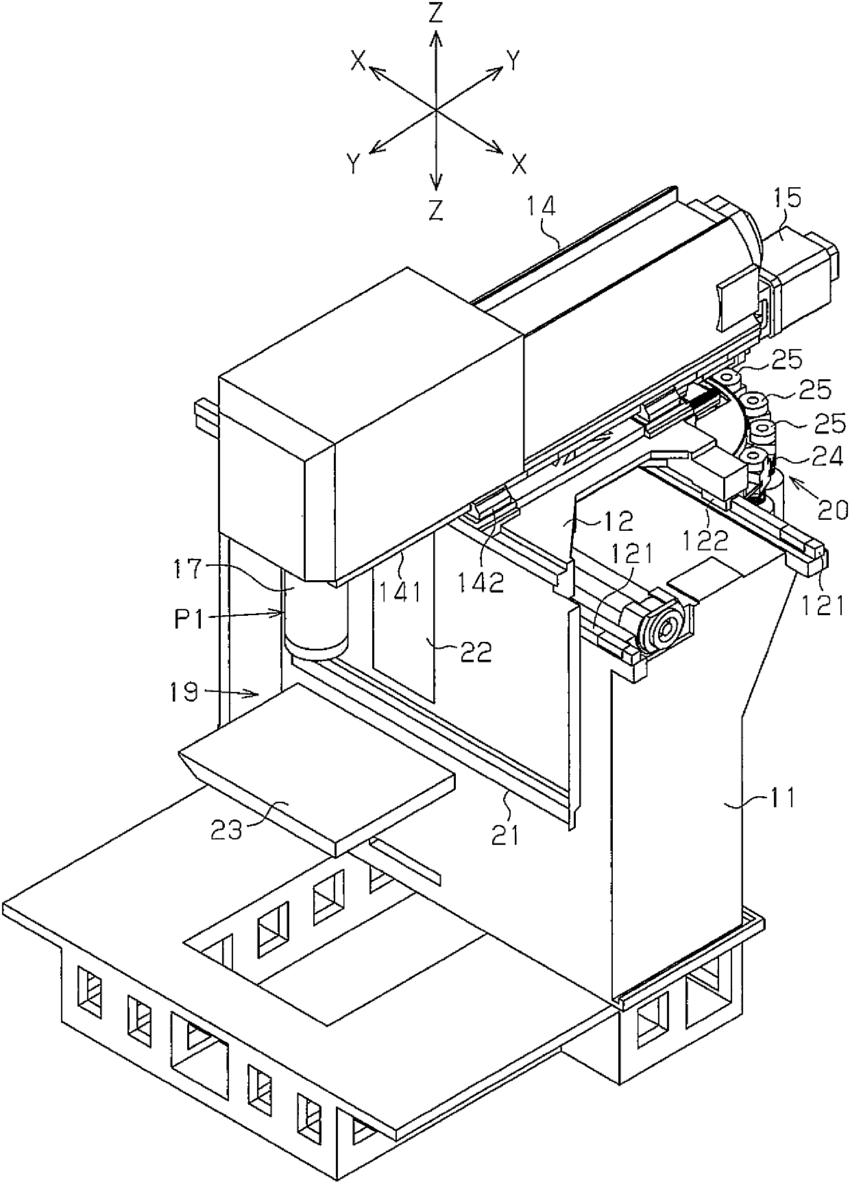
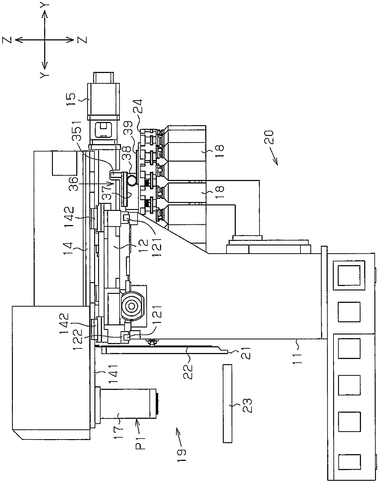
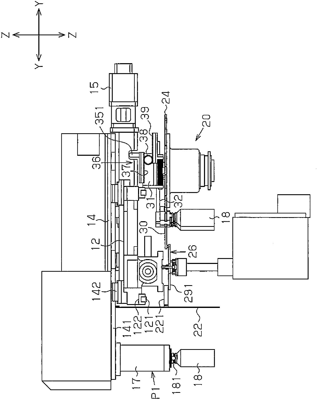
[0031] like Figure 1 ~ Figure 4 As shown, the X-axis moving table 12 is supported on the machine table 11 of the machine tool. The X-axis moving table 12 can move in the X-axis direction along the rail 121 in the horizontal plane by an X-axis moving motor (not shown). A Y-axis moving table 14 is supported on the X-axis moving table 12 . The Y-axis moving table 14 can move in the Y-axis direction in the horizontal plane along the rail 141 by the Y-axis moving motor 15 . That is, if Figure 4 As shown, a screw shaft 151 is connected to the output shaft of the Y-axis moving motor 15 capable of forward and reverse rotation. An internally threaded body 143 as a driving body is screwed onto the screw shaft 151 . The internal thread body 143 is fixed on the lower surface of the Y-axis moving table 14 . Therefore, when the internally threaded body 143 is reciprocated in the Y-axis direc...

no. 2 Embodiment approach

[0059] Next, based on Figure 11 to Figure 15 , the second embodiment will be described focusing on the parts different from the first embodiment. In the second embodiment, even if the shape, position, etc. of the members with the same reference numerals as those of the first embodiment are different from those of the first embodiment, they have the same characteristics as those of the first embodiment. Components with the same reference numbers and the like have the same function.

[0060] like Figure 11 and Figure 12 As shown, the vertical relationship between the X-axis moving table 12 and the Y-axis moving table 14 is opposite to that of the first embodiment. That is, the slider 142 of the Y-axis moving table 14 is supported on a rail 141 extending in the Y-axis direction on the machine table 11 . In addition, a slider 122 of the X-axis moving table 12 is supported on a rail 121 extending in the X-axis direction on the Y-axis moving table 14 . In the second embodime...


PUM


Abstract

The machine tool is equipped with: a tool magazine (24), which holds a plurality of tools (18) in a detachable manner; a spindle (17), which can move between a tool changing queue position and a tool changing position; and a tool changing device (26) , which performs a tool change action between the spindle (17) at the tool change position and the tool magazine (24). A connection mechanism is provided between the main shaft (17) and the tool transfer device (50), and the connection mechanism transfers the tool (18) through the movement of the main shaft (17) from the tool replacement queuing position to the tool replacement position. Since the transfer of the tool (18) is performed by the movement of the main shaft (17), a driving member such as a cylinder for driving the transfer operation of the tool (18) is not required. Therefore, a fluid pump or the like for operating the cylinder is unnecessary, and the configuration of the machine tool can be simplified.

Description

technical field [0001] The invention relates to machine tools designed to change tools between a spindle and a tool magazine. Background technique [0002] Such a machine tool is disclosed in Patent Document 1. In this conventional configuration, the tool magazine moves from the queue position to the tool replacement position corresponding to the main shaft in a state where one tool holder on the tool magazine is arranged at the index position for tool replacement. Then, by moving the tool magazine in the axial direction, the tool can be exchanged between the tool holder on the tool magazine and the spindle. [0003] prior art literature [0004] patent documents [0005] Patent Document 1: JP-A-7-214445 [0006] However, in the existing structure of Patent Document 1, it can be known from paragraph 0027 of the specification that in order to move the tool magazine between the queue position and the tool replacement position, a cylinder consisting of a cylinder is prov...

Claims


Application Information

Patent Timeline
Patent Type & Authority Patents(China)
IPC IPC(8): B23Q3/155B23Q3/157
CPCB23Q3/1554B23Q3/15766B23Q2003/155428B23Q2003/155418B23Q2003/155439
Inventor 神田明
Owner KOMATSU NTC LTD
Why Eureka
Try Eureka