Electric pressure cooker capable of automatically exhausting
A technology of electric pressure cooker and exhaust pipe, which is applied in the direction of pressure cooker, cooking utensils, household utensils, etc. It can solve the problems of increasing the difficulty of production and processing, the inability to realize automatic exhaust, and potential safety hazards of solenoid valves, so as to improve quality and reduce jamming The probability of occurrence of the phenomenon and the effect of reducing potential safety hazards
- Summary
- Abstract
- Description
- Claims
- Application Information
AI Technical Summary
Problems solved by technology
Method used
Image
Examples
Embodiment 1
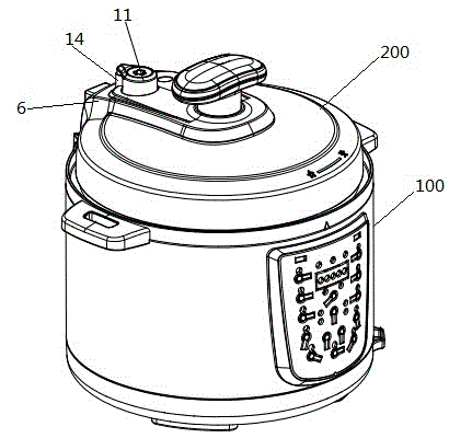
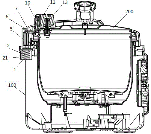
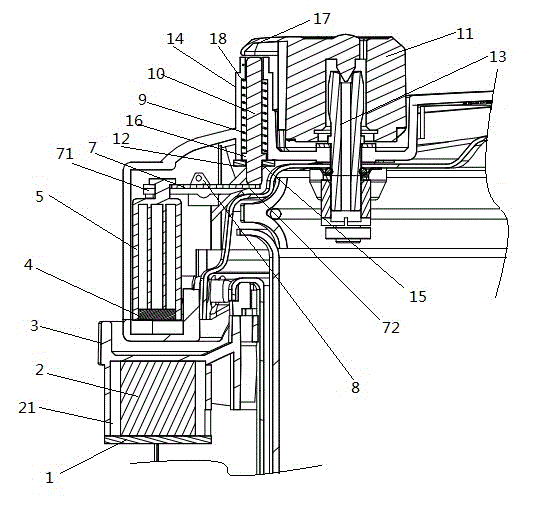
[0028] like figure 1 , figure 2 , image 3 As shown, the electric pressure cooker of the present invention includes a pot body 100, a pot cover and a control circuit (not shown in the figure), and the pot cover includes a cover body 200 and a cover 6 arranged on the cover body 200. Made and attached to the cover body 200, extending from the middle of the cover body 200 to the side wall of the cover body 200, the inside of the cover 6 is hollow, enclosing a relatively closed installation space with the cover body 200, and the cover 6 is provided with There is a pot cover handle and an exhaust pipe 13 is installed. The exhaust pipe 13 is covered with a gravity hammer 11. Specifically, the exhaust pipe 13 is surrounded by a gravity hammer installation groove, and the gravity hammer 11 is embedded in the gravity hammer. In the groove, it can move up and down along the gravity hammer installation groove. When the electric pressure cooker does not need to exhaust, the gravity ham...
Embodiment 2
[0035] This embodiment is partially improved on the basis of Embodiment 1. In this embodiment, the return spring 9 in Embodiment 1 is omitted, and the push rod 10 resets under the pressure of its own gravity and the gravity hammer 11. At the same time, in order to The push rod 10 can achieve the same technical effect as before in the absence of the return spring 9. This embodiment can also intentionally increase the quality of the push rod 10. Embedding metal materials, etc.
Embodiment 3
[0037] This embodiment simplifies its structure on the basis of Embodiment 1. This embodiment omits the guide column 14, the push rod 10 and the return spring 9 device in Embodiment 1, and the first link of the first connecting rod The two ends 72 are directly connected with the bottom of the gravity hammer 11, and the specific structure is as follows:
[0038] On the side wall of the gravity hammer installation groove, open a groove longitudinally, the second end of the first connecting rod passes through this groove, stretches into the bottom of the gravity hammer 11, when the second end of the first connecting rod goes up During the displacement, the gravity hammer 11 can be directly driven to move upwards for exhaust, and when the exhaust is not needed, the gravity hammer 11 can be reset under the gravity.
PUM
 Abstract
Description
Claims
Application Information
 - R&D
- Intellectual Property
- Life Sciences
- Materials
- Tech Scout
- Unparalleled Data Quality
- Higher Quality Content
- 60% Fewer Hallucinations
Browse by: Latest US Patents, China's latest patents, Technical Efficacy Thesaurus, Application Domain, Technology Topic, Popular Technical Reports.
© 2025 PatSnap. All rights reserved.Legal|Privacy policy|Modern Slavery Act Transparency Statement|Sitemap|About US| Contact US: help@patsnap.com


