
Bearing machining fixture mounting structure

A bearing processing and mounting structure technology, applied in the direction of manufacturing tools, metal processing equipment, metal processing mechanical parts, etc., can solve the problem of high cost, and achieve the effect of convenient operation, easy adjustment and cost reduction

Active Publication Date: 2016-07-20
GUIZHOU HONGZHOU BEARING CO LTD
View PDF9 Cites 0 Cited by
  • Summary
  • Abstract
  • Description
  • Claims
  • Application Information

AI Technical Summary

Problems solved by technology

[0002] Bearing processing generally goes through multiple processes, among which the difference between rough grinding, fine grinding, and ultra-grinding processes mainly lies in the different tooling used (different oil stones), and because of the different tooling used, the fixture clamps the workpiece to be processed The location is also different. The processing method in the prior art is generally to replace the fixture, which makes it necessary to use multiple sets of fixtures in the entire processing process, and the cost is extremely high.

Method used


Image

  • Bearing machining fixture mounting structure
  • Bearing machining fixture mounting structure

Examples


Embodiment Construction

[0013] The technical solution of the present invention is further described below, but the scope of protection is not limited to the description.

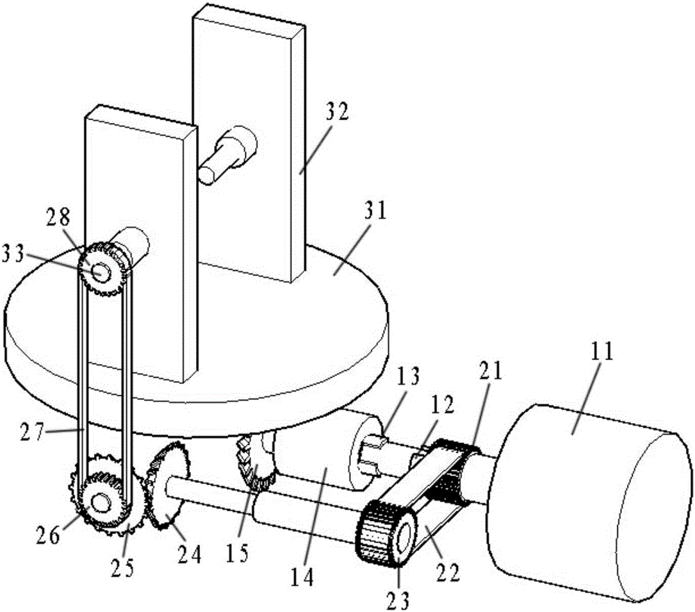
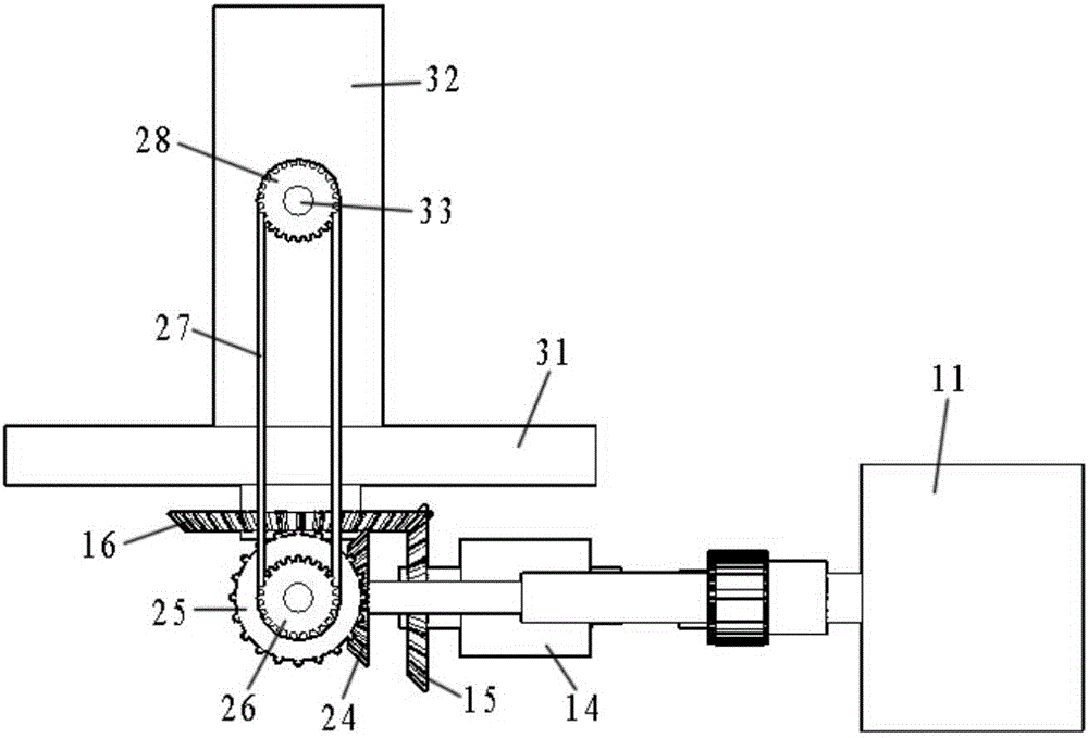
[0014] Such as figure 1 , figure 2 The shown fixture installation structure for bearing processing includes a motor 11, a disk power wheel 14, a disk driving tooth 15, a disk passive tooth 16, a first driving tooth 21, a third driven tooth 28, a workbench 31, and a splint 32 , clamp screw 33; the motor 11 is installed horizontally, and the power output shaft of the motor 11 is respectively fixed with a rear spline 12 and a front spline 13 from the rear to the front, and the rear spline 12 can mesh with the first driving tooth 21 , the front spline 13 can mesh with the disc power wheel 14, and the distance between the rear spline 12 and the front spline 13 is smaller than the distance between the first driving tooth 21 and the disc power wheel 14, so that the rear spline 12 and the front The splines 13 are not meshed and driven a...


PUM


Abstract

The invention provides a bearing machining fixture mounting structure. The structure comprises a motor, a disc power wheel, a disc driving tooth, a disc driven tooth, a first driving tooth, a third driven tooth, a worktable, a clamping plate and a clamping lead screw; the motor is horizontally mounted; a back spline and a front spline are respectively fixed on a power output shaft of the motor from back to front; the back spline can be engaged with the first driving tooth; the front spline can be engaged with the disc power wheel; the distance between the back spline and the front spline is smaller than the distance between the first driving tooth and the disc power wheel; the back spline and the front spline are asynchronously engaged for transmission; the disc driving tooth is coaxially driven at the front end of the disc power wheel; the disc driven tooth, horizontally mounted, is driven by the disc driving tooth in a right-angled engagement manner; and the disc driven tooth coaxially drives the worktable. The structure can effectively reduce the cost of enterprises in the bearing machining process through modes of easy installation, convenience for operation and capability of easily adjusting the elastic clamping degree and the horizontal position of machined parts.

Description

technical field [0001] The invention relates to a fixture installation structure used for bearing processing. Background technique [0002] Bearing processing generally goes through multiple processes, among which the difference between rough grinding, fine grinding, and super grinding processes mainly lies in the different tooling used (different oil stones), and because of the different tooling used, the fixture will clamp the workpiece to be processed The positions are also different, and the processing method in the prior art is generally to replace the fixture, which makes it necessary to use multiple sets of fixtures in the entire processing process, and the cost is extremely high. Contents of the invention [0003] In order to solve the above technical problems, the present invention provides a jig installation structure for bearing processing. The jig installation structure for bearing processing can be effectively Reduce the cost of the enterprise in the bearing ...

Claims


Application Information

Patent Timeline
IPC IPC(8): B23Q3/06
CPCB23Q3/062
Inventor 张晶磊张坤陈显富方亮孙有端
Owner GUIZHOU HONGZHOU BEARING CO LTD
Features
  • Generate Ideas
  • Intellectual Property
  • Life Sciences
  • Materials
  • Tech Scout
  • Unparalleled Data Quality
  • Higher Quality Content
  • 60% Fewer Hallucinations
Learn More