
Automatic lifting device for gluing and potting

An automatic lifting and potting technology, which is applied in the direction of lifting devices, lifting frames, etc., can solve the problems that restrict the improvement of the automation degree of the automatic filling and sealing production line of glue coating, filling and sealing, difficult automatic control of the production line, and complicated transmission mechanism, etc., to achieve The effect of stable lifting, high lifting efficiency and simple transmission mechanism

Active Publication Date: 2016-07-20
威海弘瑞智能装备有限公司
View PDF7 Cites 16 Cited by
  • Summary
  • Abstract
  • Description
  • Claims
  • Application Information

AI Technical Summary

Problems solved by technology

[0004] The present invention is aimed at the automatic lifting device for glue coating and sealing used in the automatic filling and sealing production line of existing mechanical parts and electronic devices. It is limited, which seriously restricts the technical problem of improving the automation degree of the automatic filling and sealing production line in the field of glue coating and filling. It provides a small size, simple transmission mechanism, stable lifting, high lifting efficiency, and it is easy to realize automatic control and application with the production line. It has a wide range of occasions and can well meet the requirements of the automatic filling and sealing production line in the field of glue coating and sealing. The automatic lifting device for glue coating and sealing

Method used


Image

  • Automatic lifting device for gluing and potting
  • Automatic lifting device for gluing and potting
  • Automatic lifting device for gluing and potting

Examples


Embodiment 1

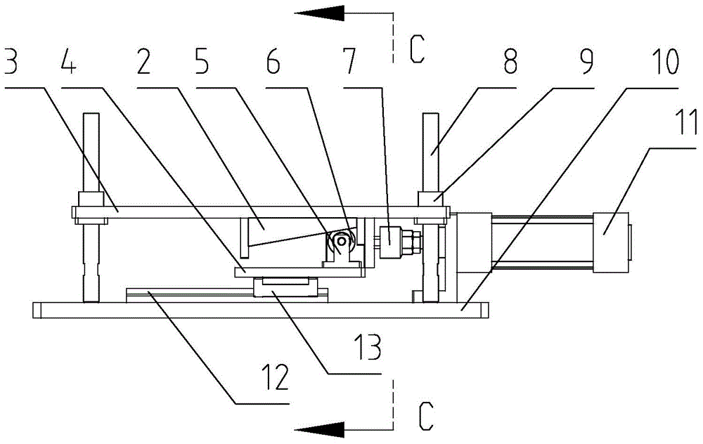
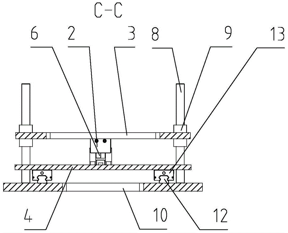
[0028] Such as figure 1 , figure 2 Shown, is an embodiment of the present invention, is provided with base 10, is fixedly provided with vertical lifting shaft 8 on base 10, is provided with linear bearing 9 on vertical lifting shaft 8, is provided with working platform 3 above base 10, and working platform 3. It is fixedly connected with the outer ring of the linear bearing 9 on the vertical lifting shaft 8. A parallel thrust plate 4 is also provided on the base 10. A sliding connection device is provided between the parallel thrust plate 4 and the base 10. figure 1 It can be seen that the sliding connection device provided between the parallel thrust plate 4 and the base 10 is fixed on the base 10 with a linear guide rail 12, the linear guide rail 12 is slidingly connected with the linear guide rail seat 13, and the linear guide rail seat 13 is connected with the parallel The thrust plate 4 is fixedly connected, and the linear guide rail 12 has a simple structure, is conven...

Embodiment 2

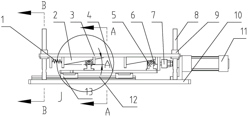
[0032] Such as image 3 , Figure 4 , Figure 5 , Figure 6 , Figure 7 , Figure 8 , Figure 9 As shown, it is another embodiment of the present invention. The difference between this embodiment and Embodiment 1 is that there are four wedge-shaped lifting thrust seats 2 at the bottom of the working platform 3, which are respectively located on the four outer peripheries of the bottom of the working platform 3. In this way, the working platform 3 can be supported stably, which is more suitable for the lifting of heavy parts. Two of the four wedge-shaped lifting thrust seats 2 are slidingly connected with the bottom surface of the working platform 3. The two wedge-shaped lifting thrust seats 2 are provided with a tension spring 1 on one side, and the tension force of the top tension spring 1 can satisfy the sliding connection between the wedge-shaped lifting seat 2 and the rollers, and can also ensure that during the lifting movement of the working platform, the mechanical...


PUM


Abstract

The invention provides an automatic lifting device for gluing and potting. By the adoption of the automatic lifting device, the technical problems that a traditional lifting machine is big in size, a transmission mechanism is complex, lifting is unstable, the lifting efficiency is low, automatic control over a production line is difficult to achieve, and the application occasions are limited are solved. The automatic lifting device is provided with a base. Vertical lifting shafts are fixedly arranged on the base. Linear bearings are arranged on the vertical lifting shafts. A working platform is arranged above the base. The working platform is fixedly connected with peripheries of the linear bearings on the vertical lifting shafts. A parallel thrust plate is further arranged on the base. A sliding connection device is arranged between the parallel thrust plate and the base. Roller seats are fixed to the parallel thrust plate. Thrust rollers are supported by the roller seats. Wedge-shaped lifting thrust bases are fixedly arranged on the bottom surface of the working platform. The thrust rollers are in rolling connection with the wedge-shaped surfaces of the wedge-shaped lifting thrust bases. A parallel movement thrust device is arranged on one side of the parallel thrust plate. The parallel movement thrust device is connected with the parallel thrust plate through a connector. The automatic lifting device can be broadly applied to the fields of gluing and potting.

Description

technical field [0001] The invention relates to a glue filling and sealing machine, in particular to an automatic lifting device for glue spreading and filling. Background technique [0002] We know that at present, the labor cost of the manufacturing industry is getting higher and higher, and the demand for robots is also increasing, which puts forward a higher demand for the degree of automation in various manufacturing fields, especially in the field of glue coating and sealing. The fully automatic potting and sealing process of electronic devices also puts forward higher requirements. In the field of glue coating and sealing, on the automatic potting and sealing production line of mechanical parts and electronic devices, there are many process steps that need to be realized by automatic lifting devices. Using automatic The lifting device completes the lifting of the parts to be processed, reaches the preset station, and completes the predetermined process operation. [...

Claims


Application Information

Patent Timeline
Patent Type & Authority Applications(China)
IPC IPC(8): B66F7/08
CPCB66F7/085
Inventor 刘恩泉李长亮
Owner 威海弘瑞智能装备有限公司
Learn More