Two-stage sludge dewatering machine

A sludge dehydrator, two-stage technology, applied in water/sludge/sewage treatment, sludge treatment, dehydration/drying/thickened sludge treatment, etc., can solve problems such as reducing compression dehydration effect, and achieve improved dehydration effect, balance the stress situation, and improve the service life

Inactive Publication Date: 2018-07-24
SUNNY ENVIRONMENTAL PROTECTION JIANGSU CO LTD
View PDF7 Cites 2 Cited by
  • Summary
  • Abstract
  • Description
  • Claims
  • Application Information

AI Technical Summary

Problems solved by technology

[0003] The above-mentioned sludge dewatering machine is the most common sludge dewatering machine, which simply adopts the auger compression method for dehydration, but during the compression process, the sludge and sewage will form a relatively stable small group, which will greatly reduce the compression. dehydration effect

Method used


Image

  • Two-stage sludge dewatering machine
  • Two-stage sludge dewatering machine

Examples


Embodiment 1

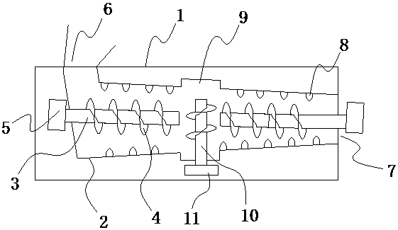
[0016] The two-stage sludge dewatering machine of this embodiment includes a horizontally arranged outer casing 1 with a closed side wall, and an inner pipe body 2 with a water-permeable side wall is horizontally arranged in the outer casing 1, and the inner pipe body 2 is arranged at intervals There are two augers formed by the agitating shaft 3 and the spirally rising agitating blades 4 arranged on the outer wall of the agitating shaft 3, the axes of the two augers are on the same straight line; the agitating shaft 3 is driven to rotate by a motor 5 connected thereto, There is a drain port on the outer shell 1, and one end of the inner pipe body 2 has a sludge feed port 6 that supplies sludge material to the stirring blade 4, and a sludge discharge that matches the top end of the stirring blade 4 is arranged on the outer shell 1 port 7; the inner diameter of the inner pipe body 2 gradually decreases from the side of the sludge feed port 6 to the side of the sludge discharge p...


PUM


Abstract

The invention aims at providing a two-section type sludge dewatering facility with a good dewatering effect.The two-section type sludge dewatering facility comprises a horizontally-arranged outer shell with a sealed side wall.An inner tube with a water-permeable side wall is horizontally arranged in the outer shell.Two augers formed by stirring shafts and spirally-ascending stirring blades arranged on the outer wall faces of the stirring shafts are arranged in the inner tube in a spaced mode.The stirring shafts are driven by external force to rotate.The outer shell is provided with a water drain opening, one end of the inner tube is provided with a sludge inlet for supplying sludge materials to the stirring blades.A sludge drain opening matched with the top ends of the stirring blades is formed in the outer shell.The two-section type sludge dewatering facility is characterized in that an expansion chamber is formed at the position, between the two augers, of the inner tube, and the diameter of the expansion chamber is larger than that of the inner tube.An auxiliary auger driven by an auxiliary driving mechanism is vertically arranged in the expansion chamber.

Description

technical field [0001] The invention belongs to the technical field of environmental protection, and in particular relates to a sludge dehydrator. Background technique [0002] The invention of patent No. 200810234499.7 discloses a sludge dewatering machine, which includes an outer shell with a closed side wall, an inner tube body with a water-permeable side wall is arranged in the outer shell body, and a stirring shaft and an outer shell of the stirring shaft are arranged in the inner tube body. The wall is provided with an auger formed by spirally rising stirring blades. The stirring shaft is driven to rotate by external force. There is a drain port on the outer shell, and the inner pipe body has a sludge feed port for supplying sludge materials to the stirring blades. A sludge discharge opening matched with the top end of the stirring blade is provided, and a brush is provided on the outer edge of the stirring blade, and the bristles of the brush contact the inner wall su...

Claims


Application Information

Patent Timeline
Patent Type & Authority Patents(China)
IPC IPC(8): C02F11/12
CPCC02F11/121C02F2303/06
Inventor 邹剑张建军李傲
Owner SUNNY ENVIRONMENTAL PROTECTION JIANGSU CO LTD
Why Eureka
Try Eureka