Turnover device and combined screen system

A combined screen and movable frame technology, applied in the direction of identification devices, instruments, supporting machines, etc., can solve the problems of inconvenient maintenance and maintenance, and achieve the effect of easy maintenance and repair.

Active Publication Date: 2016-07-20
BEIJING TIMES OSEE TECH CO LTD
View PDF9 Cites 1 Cited by
  • Summary
  • Abstract
  • Description
  • Claims
  • Application Information

AI Technical Summary

Problems solved by technology

[0004] The purpose of the present invention is to provide a turning device to so

Method used


Image

  • Turnover device and combined screen system
  • Turnover device and combined screen system
  • Turnover device and combined screen system

Examples


Embodiment Construction

[0026] The technical solutions of the present invention will be clearly and completely described below in conjunction with the accompanying drawings. Apparently, the described embodiments are some of the embodiments of the present invention, but not all of them. Based on the embodiments of the present invention, all other embodiments obtained by persons of ordinary skill in the art without making creative efforts belong to the protection scope of the present invention.

[0027] In the description of the present invention, it should be noted that the terms "center", "upper", "lower", "left", "right", "vertical", "horizontal", "inner", "outer" etc. The indicated orientation or positional relationship is based on the orientation or positional relationship shown in the drawings, and is only for the convenience of describing the present invention and simplifying the description, rather than indicating or implying that the referred device or element must have a specific orientation, ...


PUM


Abstract

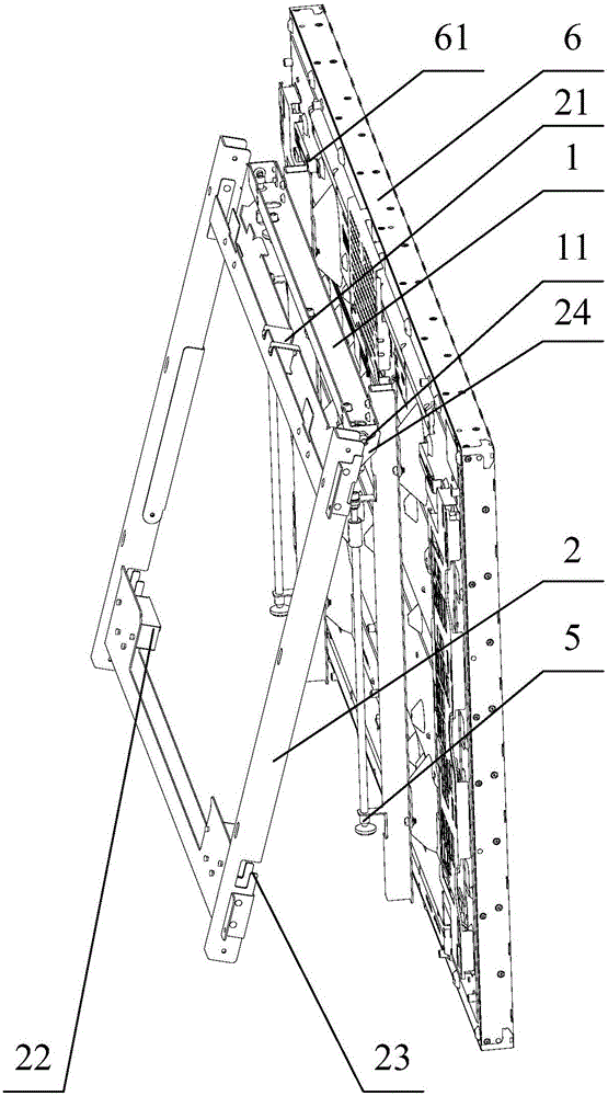
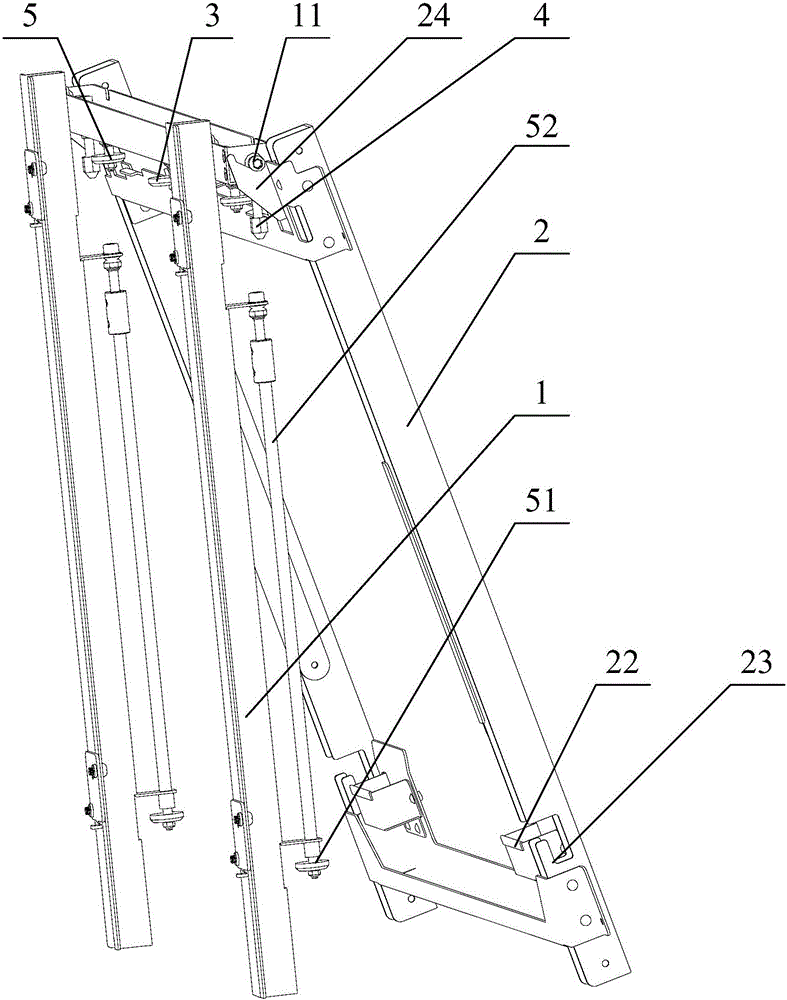
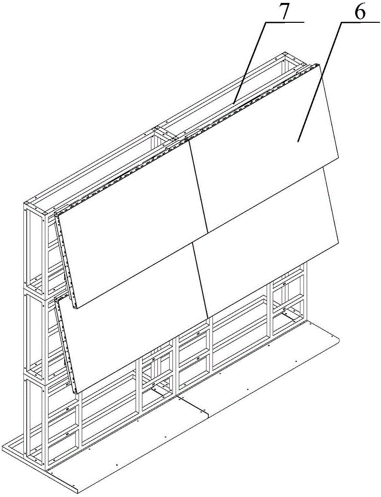
The invention relates to the technical field of splicing mounting of combined screen systems, in particular to a turnover device and a combined screen system. The device comprises movable frames and fixed frames. The movable frames are hung on the fixed frames. Rotary shafts are arranged at the upper ends of the movable frames. Supporting parts for supporting the rotary shafts are arranged at the upper ends of the fixed frames. The movable frames are used for supporting display units, and the fixed frames are used for being fixed to an outer fixed object. According to the turnover device, maintenance personnel can rotate the display units relative to the fixed frames without assistance of any external tool, and therefore operation space is provided for the maintenance personnel, and later maintenance and repairing are convenient for the maintenance personnel.

Description

technical field [0001] The invention relates to the technical field of splicing and installation of a combined screen system, in particular to a flipping device and a combined screen system. Background technique [0002] Combined screen system splicing refers to dividing a complete image signal into N blocks and then assigning them to N video display units. At present, the splicing methods of combined screen systems in the prior art mainly adopt DLP splicing, projection seamless fusion splicing and ultra-narrow bezel LCD splicing. Among them, the ultra-narrow LCD screen splicing method uses the ultra-narrow physical edge LCD screen as the display unit, and combines the splicing display units in the form of N rowsⅹN columns to form a display screen, realizing the display mode of the super-combined screen system. [0003] However, in the combined screen system in the prior art, during the splicing process, the display unit is fixed on the bracket or the wall through connectin...

Claims


Application Information

Patent Timeline
IPC IPC(8): F16M11/06F16M11/18G09F9/302
CPCF16M11/06F16M11/18G09F9/3026
Inventor 徐宇朱利人徐道武陈润海
Owner BEIJING TIMES OSEE TECH CO LTD
Why Eureka
Try Eureka