Less-switch five-power level voltage source type inverter and control method thereof

A technology of voltage source type and inverter device, applied in the field of multi-level voltage source type inverter, can solve the problems of complex topology structure and control method of multi-level power conversion circuit, achieve easy maintenance and repair, simple control method, The effect of reducing the amount of use

Inactive Publication Date: 2008-05-07
黑龙江工商职业技术学院
View PDF0 Cites 17 Cited by
  • Summary
  • Abstract
  • Description
  • Claims
  • Application Information

AI Technical Summary

Problems solved by technology

[0003] The purpose of the present invention is to solve the problem that the topology structure and control method of the existing multi-level power conversion circuit are relatively complicated, and the practical application of multi-level inverters is suppressed.

Method used


Image

  • Less-switch five-power level voltage source type inverter and control method thereof
  • Less-switch five-power level voltage source type inverter and control method thereof

Examples


specific Embodiment approach 1

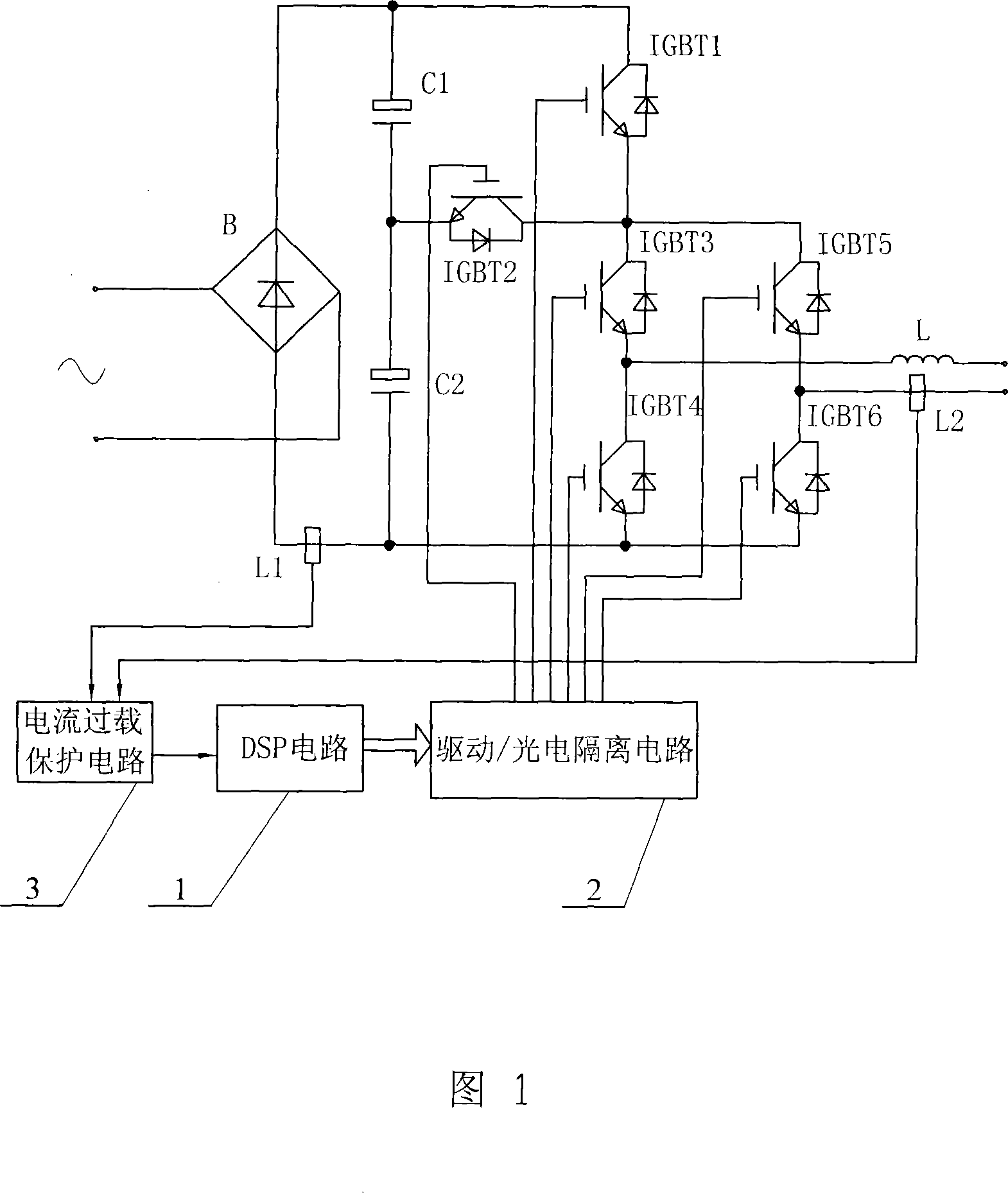
[0018] Specific Embodiment 1: This embodiment is described in conjunction with accompanying drawing 1. This embodiment consists of rectifying full bridge B, electrolytic capacitor C1, electrolytic capacitor C2, IGBT1 (insulated gate bipolar transistor), IGBT2, IGBT3, IGBT4, IGBT5, IGBT6, Inductor L, DSP circuit 1, drive / photoelectric isolation circuit 2;

[0019] The two AC input terminals of the rectified full bridge B are connected to the output terminal of the AC power supply, the positive terminal of the rectified full bridge B and the positive terminal of the electrolytic capacitor C1 are connected to the collector of IGBT1, the negative terminal of the electrolytic capacitor C1 and the emitter of IGBT2 are connected to the electrolytic capacitor The positive terminal of C2, the collector of IGBT2, the emitter of IGBT1, and the collector of IGBT3 are connected to the collector of IGBT5, the emitter of IGBT3 and the collector of IGBT4 are connected to one end of the inducto...

specific Embodiment approach 2

[0028] Specific embodiment 2: This embodiment is described in conjunction with accompanying drawing 1. This embodiment adds a current transformer L1, a current transformer L2, and a current overload protection circuit 3 on the basis of the specific embodiment 1;

[0029] The current transformer L1 is set on the negative terminal of the rectified full bridge B, the current transformer L2 is set on the second output end of the inverter device, and the signal output end of the current transformer L1 and the signal output end of the current transformer L2 are respectively connected to The two signal input terminals of the current overload protection circuit 3 and the control signal output terminal of the current overload protection circuit 3 are connected to the current overload protection control signal input terminal of the DSP circuit 1 .

[0030] This implementation mode can realize the protection of current overload and current impact of IGBT1, IGBT2, IGBT3, IGBT4, IGBT5, IGBT...

specific example

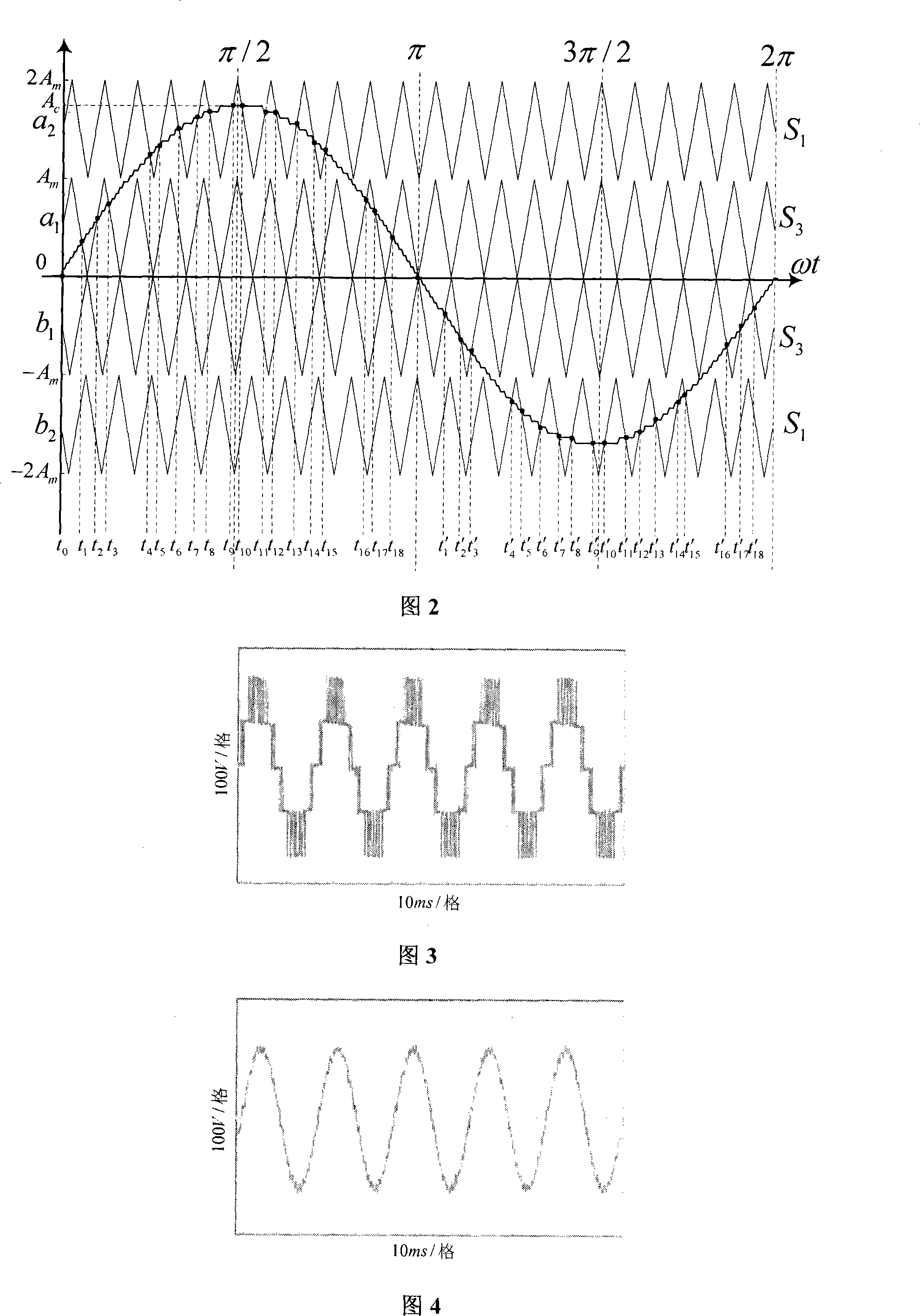
[0032] Specific example: Select Fuji's IGBT1-6 modules as 2MBI25L-120 for the power switch tube, the maximum pressure is 1200 volts, and the maximum overcurrent is 25 amps. The drive / photoelectric isolation circuit 2 mainly adopts the M57962 of Mitsubishi Corporation, and builds the drive and protection circuit on this basis. The filter inductance L of the inverter is 10mH, and the DC side voltage of the rectified full bridge B is Ed c1 =E dc2 =150V, the switching frequency is 1075Hz. The core of the control unit of DSP circuit 1 is composed of TMS320F2812. Combined with Figure 3 and Figure 4, there are five different level outputs (0, ±150V, ±300V). And do frequency spectrum analysis on it, calculate the 19th harmonic, get its THD=9.50% after calculation, its harmonic mainly concentrates on the 15th and 17th. It can be seen from Figure 4 that the load resistor voltage after the filter inductor is relatively close to sinusoidal. Do frequency spectrum analysis on the volta...


PUM


Abstract

A five-level voltage source inverting device with few switches and a control method thereof relate to the technological field of a multilevel voltage source inversion, aiming to solve the problem that the complicated topological structure and the control method of a prior multilevel power conversion circuit limit the application of the multilevel inverter in actual usage. The tandem connected C1 and C2 are in bridge connection with the two output ends of the rectifier bridge B, one output end of which is connected with one input end of an H type bridge component consisting of an IGBT3-6 through a voltage control component consisting of an IGBT1-2, the other input end of the H type bridge component is connected with the other output end of the rectifier bridge B. The method and the procedures are as follows, set t0-t18, and t1'-t18' as the time when the positive half, the negative half of a sine wave and a triangular wave cross. A DSP circuit (1) controls the IGBT1-6 through a driving/ photoelectric isolation circuit (2) to conduct or close according to the time t0-t18, and t1'-t18'. The circuit structure of the present invention uses fewer components, the control method is simple and reacts rapidly, and therefore the present invention can be widely promoted.

Description

technical field [0001] The invention relates to the technical field of multilevel voltage source inverter. Background technique [0002] In recent years, with the comprehensive development of power electronics and control technology, power electronic devices have been widely used. People have increasingly strong requirements for high voltage, high power, high frequency, and low harmonic disturbance of power electronic devices. Multilevel inverters have the characteristics of large power capacity, low switching frequency, small output harmonics, fast response, and good electromagnetic compatibility. It can also make fully controlled power electronic devices with lower withstand voltages reliably applied to high-voltage and high-power fields, and effectively reduce high-order harmonics generated by PWM control. However, the topology and control methods of multi-level power conversion circuits are more complex. Complicated, it inhibits the promotion and use of multi-level inv...

Claims


Application Information

Patent Timeline
Patent Type & Authority Applications(China)
IPC IPC(8): H02M7/537H02M1/32H02H7/122
Inventor 曾繁鹏
Owner 黑龙江工商职业技术学院
Why Eureka
Try Eureka