
Regulating circuit and method for voltage output

A technology of regulating circuit and voltage output, applied in the direction of regulating electrical variable, output power conversion device, control/regulation system, etc., can solve the problem of incompatibility of output voltage regulating circuit interface, and achieve the effect of compatible analog and digital regulation

Active Publication Date: 2017-09-22
CHIPONE TECH BEIJINGCO LTD
View PDF5 Cites 0 Cited by
  • Summary
  • Abstract
  • Description
  • Claims
  • Application Information

AI Technical Summary

Problems solved by technology

[0006] The embodiment of the present invention provides a voltage output adjustment circuit and method to at least solve the technical problem that the output voltage adjustment circuit interface is not compatible because the adjustment of the output value can only be completed in the communication mode in the prior art

Method used


Image

  • Regulating circuit and method for voltage output
  • Regulating circuit and method for voltage output
  • Regulating circuit and method for voltage output

Examples


Embodiment 1

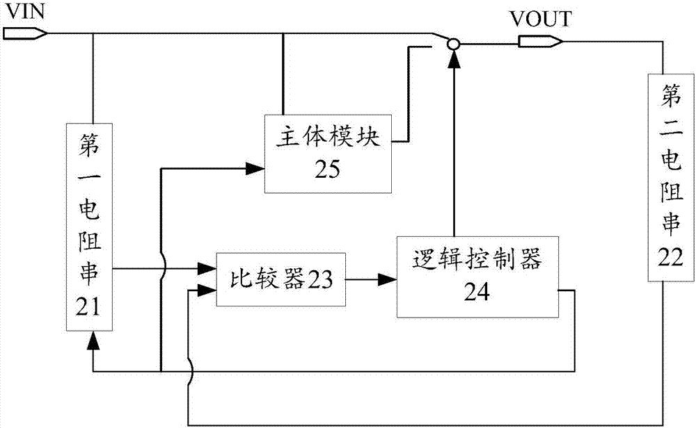
[0019] According to an embodiment of the present invention, an embodiment of a voltage output regulating circuit is provided, figure 2 It is a structural schematic diagram of a voltage output regulating circuit according to an embodiment of the present invention, such as figure 2 As shown, the regulating circuit includes: a first resistor string 21, a second resistor string 22, a comparator 23, a logic controller 24 and a main module 25, wherein,

[0020] The comparator 23 is electrically connected to the first resistor string 21 and the second resistor string 22 respectively, and is used to compare whether the first resistor voltage of the first resistor string 21 is greater than the second resistor voltage of the second resistor string 22;

[0021] The logic controller 24 is electrically connected to the first resistor string 21 and the comparator 23 respectively, and is used to control the comparator 23 to traverse and compare the voltage value between the first resistor ...

Embodiment 2

[0041] According to an embodiment of the present invention, an embodiment of a method for adjusting voltage output is provided. It should be noted that the steps shown in the flow chart of the accompanying drawings can be executed in a computer system such as a set of computer-executable instructions, and, Although a logical order is shown in the flowcharts, in some cases the steps shown or described may be performed in an order different from that shown or described herein.

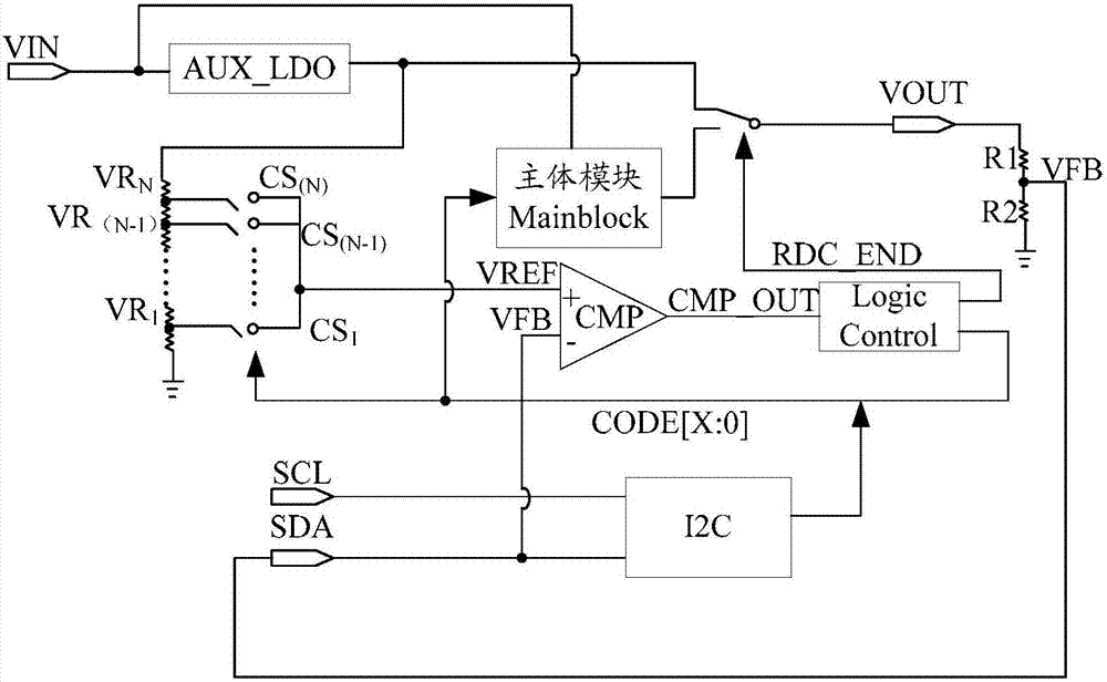
[0042] Figure 4 is a schematic flowchart of a method for adjusting voltage output according to an embodiment of the present invention, which is applied to figure 2 with image 3 any of the regulation circuits shown in the voltage output, such as Figure 4 As shown, the method includes the following steps:

[0043] Step S402, the comparator receives the first resistor voltage output by the first resistor string and the second resistor voltage output by the second resistor string;

[0044] Step S404,...


PUM


Abstract

The invention discloses a voltage output adjusting circuit and method, wherein the adjusting circuit comprises: a comparator, electrically connected respectively with a first resistor string and a second resistor string and used for comparing whether a first resistance voltage of the first resistor string is greater than a second resistance voltage of the second resistor string; a logic controller, electrically connected respectively with the first resistor string and the comparator and used for controlling the comparator to traverse and compare voltage values of the first and second resistor strings; a main module, electrically connected with the logic controller and used for storing a corresponding code value when the first resistance voltage is greater than the second resistance voltage and recording an output voltage corresponding to the code value. The technical problem that since output values can be adjusted only in a communication manner in the prior art, the circuit structure is unable to be compatible when compared to existing voltage dividers is solved.

Description

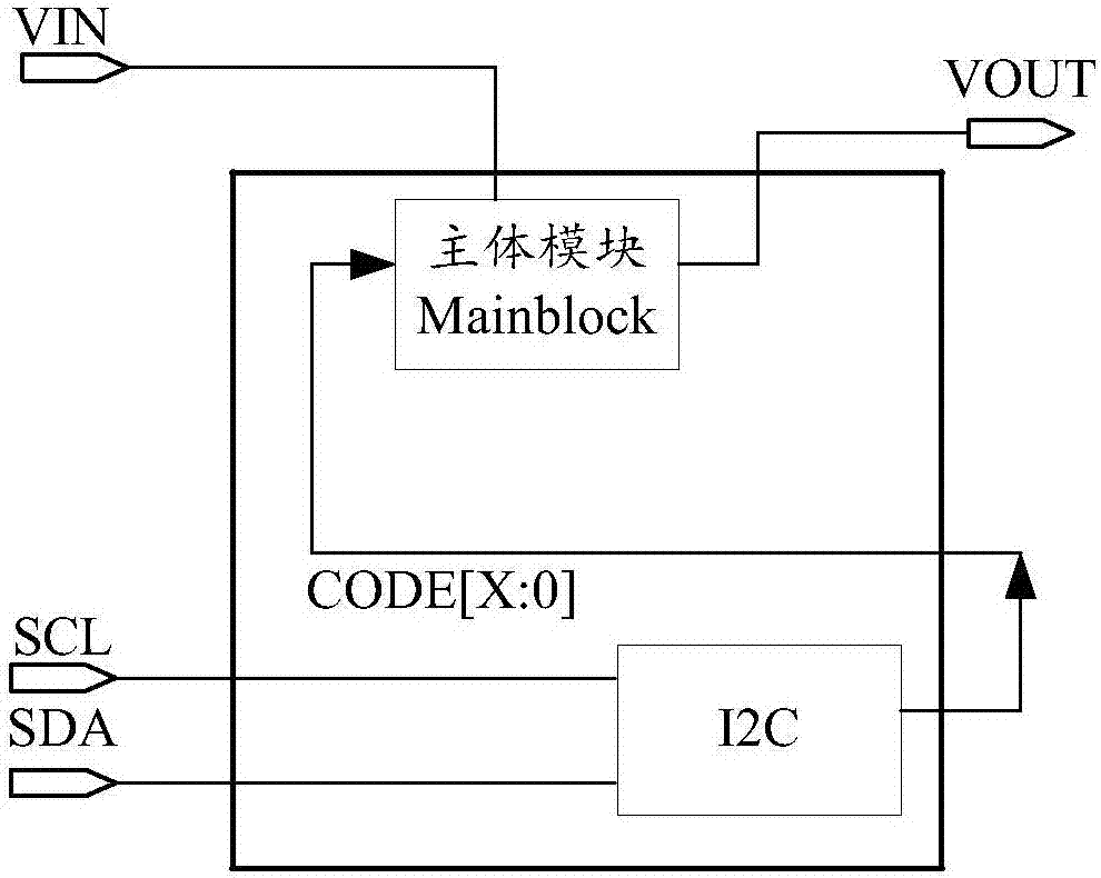
technical field [0001] The invention relates to the application field of electrical technology, in particular, to a voltage output regulating circuit and method. Background technique [0002] With the widespread application of digital interface technology, many products use digital interface to adjust the output value of the system. How to design two voltage regulation schemes compatible with analog and digital regulation has become an urgent problem to be solved today. [0003] figure 1 It is a structural schematic diagram of the communication bus chip architecture in the prior art, such as figure 1 As shown, in the black thick line area is the traditional I2C communication bus chip architecture, the customer adjusts the CODE[x:0] value of x+1 bit through the SDA / SCL two buses. This CODE value is input into the main module Mainblock. According to different CODE[x:0], the user can obtain different output values ​​of the output voltage VOUT. [0004] It can be seen from t...

Claims


Application Information

Patent Timeline
Patent Type & Authority Patents(China)
IPC IPC(8): G05F1/46H02M3/156
CPCG05F1/46H02M3/156
Inventor 李东金宁
Owner CHIPONE TECH BEIJINGCO LTD
Learn More