A chip feeding mechanism and chip bonder

A chip and feeding technology, applied in the direction of conveyor objects, electrical components, transportation and packaging, etc., can solve the problems of affecting the speed of bonding chips, welding arm weight, and low speed, so as to improve the bonding speed and bonding accuracy, Improved consistency and product quality, low system cost

Inactive Publication Date: 2020-05-05
CETC BEIJING ELECTRONICS EQUIP
View PDF6 Cites 0 Cited by
  • Summary
  • Abstract
  • Description
  • Claims
  • Application Information

AI Technical Summary

Problems solved by technology

In addition, the linear motor, linear encoder and other parts are all loaded on the welding arm, which makes the welding arm very heavy, and the acceleration is difficult to increase, which seriously affects the bonding speed.
[0004] Based on the above, whether it is a spline bearing type or a linear motor type, the pick-and-place arm is usually heavy, with poor stiffness, uncontrollable force, high cost, poor chip adhesion accuracy, and low speed

Method used


Image

  • A chip feeding mechanism and chip bonder
  • A chip feeding mechanism and chip bonder
  • A chip feeding mechanism and chip bonder

Examples


Embodiment Construction

[0042] In order to make the technical problems, technical solutions and advantages to be solved by the present invention clearer, the following will describe in detail with reference to the drawings and specific embodiments.

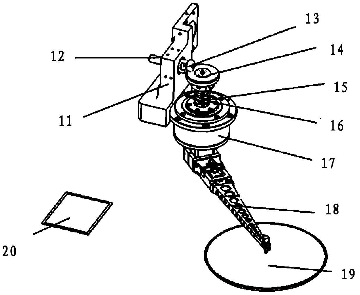
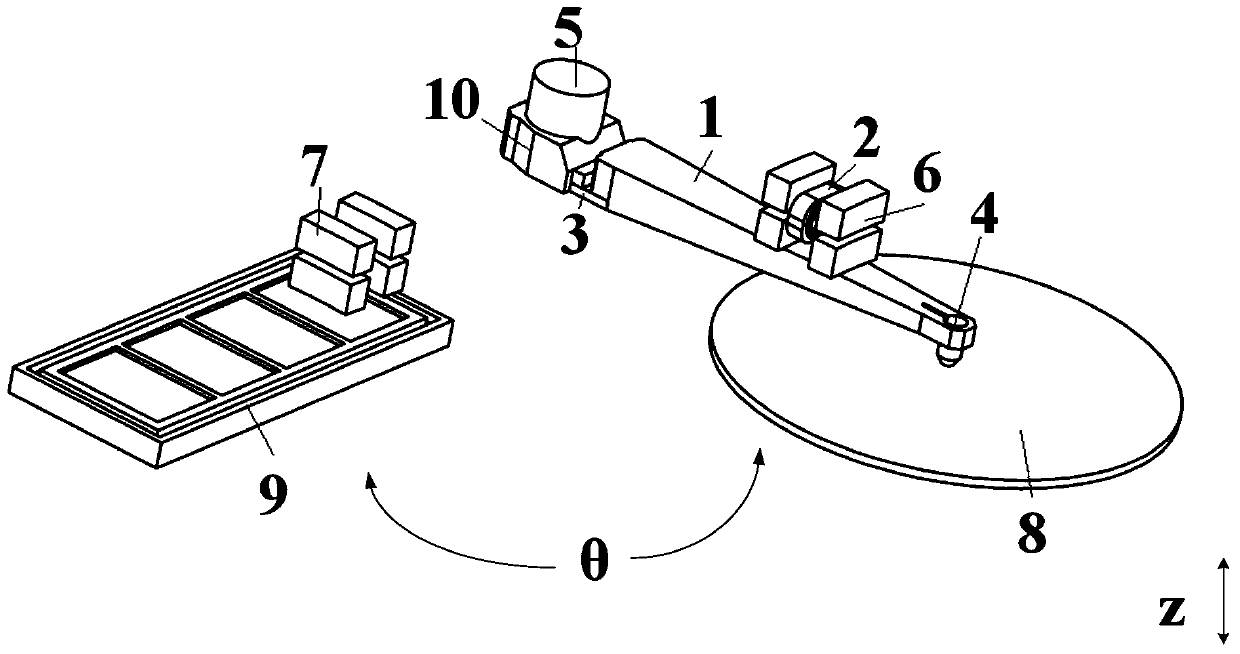
[0043] In view of the defects of the traditional chip feeding mechanism, such as image 3 As shown, the embodiment of the present invention provides a chip feeding mechanism, which includes:

[0044] Rotating device capable of rotating around the axis;

[0045] a welding arm unit distributed on the rotating device around the axis of the rotating device;

[0046] The first driving device is used to drive the welding arm unit rotating to the picking area to pick up chips from the picking area, and to drive the welding arm unit rotating to the placing area to place chips into the placing area.

[0047] Among them, the rotating device, such as image 3 or Figure 4 or Figure 5 As shown, it includes a bearing 5 that rotates around the axis and a sleeve ...


PUM


Abstract

The invention provides a chip supplying and feeding mechanism and a chip bonder, relating to the field of mechanical manufacturing. The chip supplying and feeding mechanism comprises a rotation device, a welding arm unit and a first driving device, wherein the rotation device can do rotation movement around an axis, the welding arm unit is arranged on the rotation device around the axis of the rotation device, and the first deriving device is used for driving the welding arm unit to rotating to a chip pickup region to pick up a chip from the chip pickup region and driving the welding arm unit rotating to a chip placing region to place the chip on the chip placing region. In the chip supplying and feeding mechanism, Theta-direction rotation and Z-direction reciprocating movement are achieved respectively by two driving modes, a spline bearing with expensive cost and high precision requirement is removed, and high rigidity of a pickup and placing arm and low system cost are ensured. With the mode of chip pickup and placing, the bonding speed and the bonding precision of the chip bonder are greatly improved, and the consistency of a machine and the product quality are improved.

Description

technical field [0001] The invention relates to the field of mechanical manufacturing, in particular to a chip feeding mechanism and a chip bonding machine. Background technique [0002] There are two common types of traditional chip bonding mechanism (also called chip feeding mechanism). One is to use the spline bearing to drive the pick-and-place arm to rotate in the θ direction and reciprocate in the Z direction to pick and place the film, such as figure 1 shown. The motor drive is installed on the eccentric shaft 12 of the eccentric shaft seat 11. Bearing 13 is installed on eccentric shaft 12 axle ends, to reduce the frictional resistance when mechanism runs. The gland 14 and chip pick-and-place arm 18 are fixed on the splined shaft 16 . The splined shaft 16 is installed on the bearing seat 17 to move in Z direction and θ direction. When picking up the chip, the bearing 13 pushes the gland 14, drives the spline shaft 16 and the chip pick-and-place arm 18 to move dow...

Claims


Application Information

Patent Timeline
Patent Type & Authority Patents(China)
IPC IPC(8): H01L21/677H01L21/67
Inventor 于丽娜
Owner CETC BEIJING ELECTRONICS EQUIP
Why Eureka
Try Eureka