Mobile terminal and antenna structure thereof

A technology of antenna structure and feed port, which is applied to antennas, antenna parts, antenna supports/mounting devices, etc., can solve problems such as unfavorable performance, and achieve the effects of small structure size, strong practicability, and small space

Inactive Publication Date: 2016-07-20
ONEPLUS TECH SHENZHEN
View PDF4 Cites 58 Cited by
  • Summary
  • Abstract
  • Description
  • Claims
  • Application Information

AI Technical Summary

Problems solved by technology

The metal frame mobile phone antenna solution is often not conducive to performance due to the size of the antenna space available on the device

Method used


Image

  • Mobile terminal and antenna structure thereof
  • Mobile terminal and antenna structure thereof
  • Mobile terminal and antenna structure thereof

Examples


Embodiment Construction

[0028] In order to make the object, technical solution and advantages of the present invention clearer, the specific implementation manners of the mobile terminal and its antenna structure of the present invention will be described below with reference to the accompanying drawings. It should be understood that the specific embodiments described here are only used to explain the present invention, not to limit the present invention.

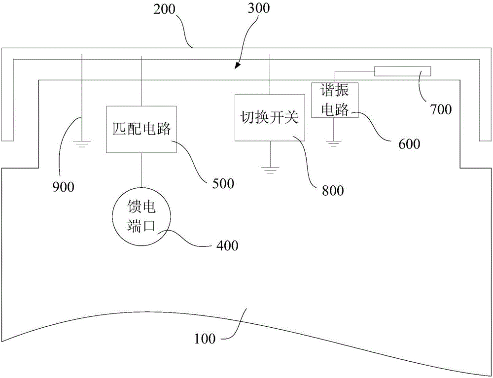
[0029] see figure 1 , in one embodiment, the antenna structure can be used as a back shell, including a metal floor 100 , a metal frame 200 , a feed port 400 , a matching circuit 500 , a resonant circuit 600 and a parasitic branch 700 . A gap 300 with a width of 0.5 mm to 3 mm is provided between the metal floor 100 and the metal frame 200 . The feed port 400 is electrically connected to the metal floor 100 , and is electrically connected to the metal frame 200 through the matching circuit 500 . One end of the parasitic stub 700 is electrically ...


PUM


Abstract

The present invention discloses an antenna structure. The antenna structure is used for taking ad a base shell and comprises a metal floor, a metal frame, a feeding port, a matching circuit, a resonance circuit and a parasitic branch knot. A slit with a width in the range from 0.5mm to 3mm is arranged between the metal floor and the metal frame; the feeding port is electrically connected with the metal floor and is electrically connected with the metal frame through the matching circuit; and one end of the parasitic branch knot is electrically connected with the metal floor through the resonance circuit. The antenna structure is able to realize multi-band frequency work, and is small in size and required space and high in practicality. The present invention further discloses a mobile terminal with the antenna structure.

Description

technical field [0001] The present invention relates to the technical field of antennas, in particular to a mobile terminal and its antenna structure. Background technique [0002] To meet the demand for small wireless devices, manufacturers are constantly striving to realize wireless communication circuits, such as antenna assemblies, in compact structures. At the same time, it may be desirable to include conductive structures in electronic devices, such as metal device housing components. Because conductive components can affect radio frequency performance, care must be taken when incorporating antennas into electronic devices that include conductive structures. The metal frame mobile phone antenna solution is often not conducive to performance due to the size of the antenna space available on the device. Contents of the invention [0003] Based on this, it is necessary to provide an antenna structure capable of working in multiple frequency bands and having a small si...

Claims


Application Information

Patent Timeline
Patent Type & Authority Applications(China)
IPC IPC(8): H01Q1/24H01Q1/44H01Q5/10
CPCH01Q1/24H01Q1/242H01Q1/44H01Q5/10
Inventor 母明周昌文张大印
Owner ONEPLUS TECH SHENZHEN
Why Eureka
Try Eureka