Power system emergency reserve capacity configuration method

A technology of emergency reserve capacity and reserve capacity, which is applied in the direction of power network operating system integration, circuit devices, information technology support systems, etc., can solve the problem of system frequency drop, unbalanced power generation power and load power, and failure to ensure safe and stable operation of the power system and other issues to achieve the effect of ensuring safety and improving the level of transient safety

Inactive Publication Date: 2016-07-20
DALIAN UNIV OF TECH
View PDF3 Cites 12 Cited by
  • Summary
  • Abstract
  • Description
  • Claims
  • Application Information

AI Technical Summary

Problems solved by technology

[0004] After the accident, the power shortage caused by the accident will lead to the imbalance of power generation and load power, especially when a large-scale DC blocking fault occurs, the system frequency will drop significantly, and the safe and stable operation of the power system cannot be guaranteed.

Method used


Image

  • Power system emergency reserve capacity configuration method
  • Power system emergency reserve capacity configuration method
  • Power system emergency reserve capacity configuration method

Examples


Embodiment Construction

[0048] In order to make the purpose, technical solutions and advantages of the embodiments of the present invention clearer, the technical solutions in the embodiments of the present invention will be clearly and completely described below in conjunction with the drawings in the embodiments of the present invention. Obviously, the described embodiments It is a part of embodiments of the present invention, but not all embodiments. Based on the embodiments of the present invention, all other embodiments obtained by persons of ordinary skill in the art without creative efforts fall within the protection scope of the present invention.

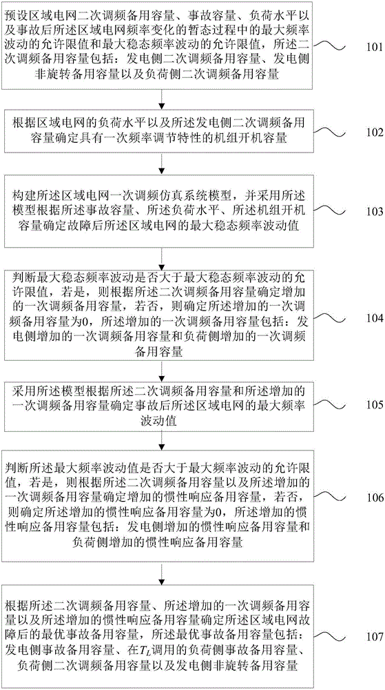
[0049] figure 1 It is a flow chart of the power system accident reserve capacity configuration method of the present invention, as figure 1 As shown, the method of this embodiment includes:

[0050] Step 101. Preset the secondary frequency regulation reserve capacity R of the regional power grid 2 , the accident capacity, the load level and the...


PUM


Abstract

The present invention provides a power system emergency reserve capacity configuration method. The method comprises: a system secondary frequency modulation reserve R2 is determined according to a cost effectiveness method; the system secondary frequency modulation reserve R2 is taken as a basis, and the maximum steady state frequency fluctuation [Delta]fw,0 of a system after the occurrence of an extra high-voltage direct current bipolar locking fault is simulated and determined; if the [Delta]fw,0 is larger than an allowable limit, a generation side and a load side are taken as reserved sources, a lowest cost is the standard, and an added primary frequency modulation reserve [Delta]R1,w is determined, or else, the [Delta]R1,w is equal to zero; the R2 and the [Delta]R1,w are taken as a basis, the maximum frequency fluctuation [Delta]fh,0 of the system after the occurrence of an extra high-voltage direct current bipolar locking fault is simulated and determined; if the [Delta]fh,0 is larger than an allowable limit, the generation side and the load side are taken as reserved sources, the lowest cost is the standard, and an added inertia response reserve [Delta]R1,h is determined, or else, the [Delta]R1,h is equal to zero; and finally, an optimum emergency reserve capacity R in an electrical area in the whole process of frequency fluctuation after a large-scale direct current locking fault is determined. The power system emergency reserve capacity configuration method is able to improve the transient state safety level of a system after the occurrence of faults so as to comprehensively guarantee the safety of the system after the occurrence of faults.

Description

technical field [0001] Embodiments of the present invention relate to the technical field of electric power system dispatching, and in particular, to a method for configuring emergency reserve capacity of electric power systems. Background technique [0002] The formulation of backup plan is one of the important means to maintain the reliability level of the power system and ensure the safe and stable operation of the system, and the method of determining the emergency backup capacity is the main content. [0003] In the prior art, a deterministic method is generally used to determine the emergency reserve capacity of the system, that is, it is determined according to the maximum unit capacity in the system or a certain percentage (generally 8% to 10%) of the peak load of the system. The current determination method for emergency reserve capacity defines the relevant requirements for emergency reserve capacity from the perspective of total reserve capacity, that is, mainly f...

Claims


Application Information

Patent Timeline
Patent Type & Authority Applications(China)
IPC IPC(8): H02J3/24H02J3/46H02J3/14
CPCH02J3/002H02J3/14H02J3/24H02J3/46H02J2203/20Y02B70/3225Y04S20/222
Inventor 李卫东董浩宇王海霞吕泉巴宇刘娆
Owner DALIAN UNIV OF TECH
Why Eureka
Try Eureka