Image processing method and electronic device

A technology of image processing and electronic devices, applied in image communication, electrical components, editing/combining graphics or text, etc., can solve problems such as dizziness and eye fatigue, and achieve the effect of simple cost

Inactive Publication Date: 2016-07-20
LITE ON ELECTRONICS (GUANGZHOU) LTD +1
View PDF5 Cites 4 Cited by
  • Summary
  • Abstract
  • Description
  • Claims
  • Application Information

AI Technical Summary

Problems solved by technology

[0003] However, the above display methods usually require additional hardware, and when the two eyes see different images, it may cause people's eyes to be tired, and even cause problems such as dizziness

Method used


Image

  • Image processing method and electronic device
  • Image processing method and electronic device
  • Image processing method and electronic device

Examples


Embodiment 1

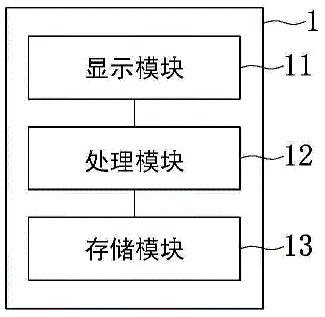
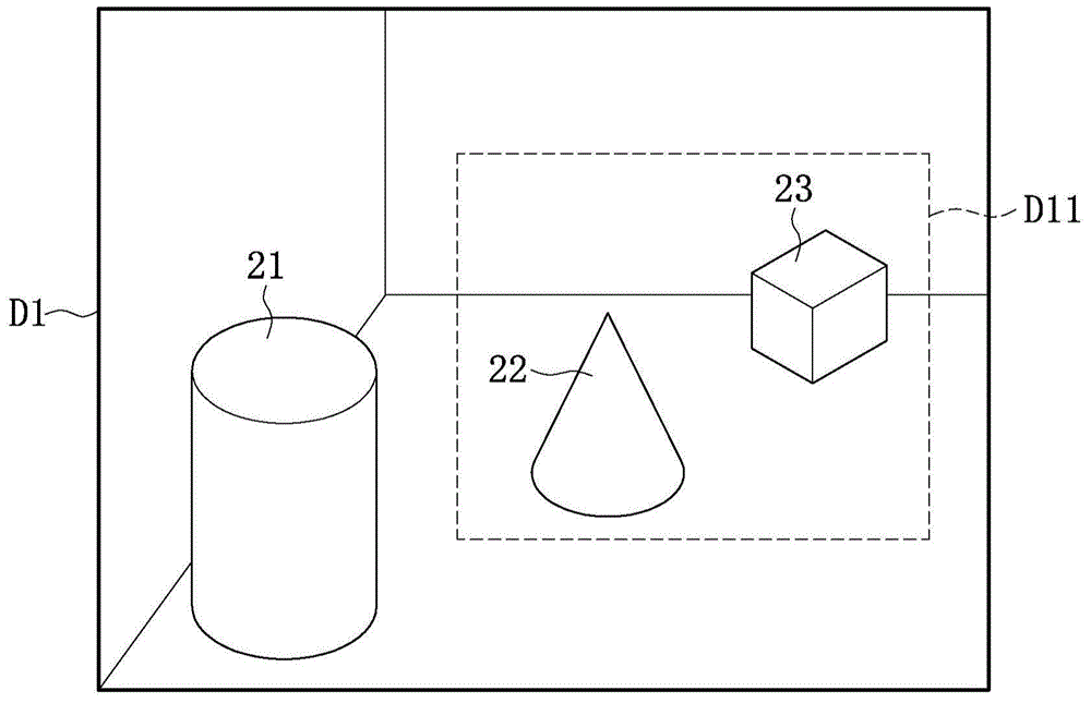
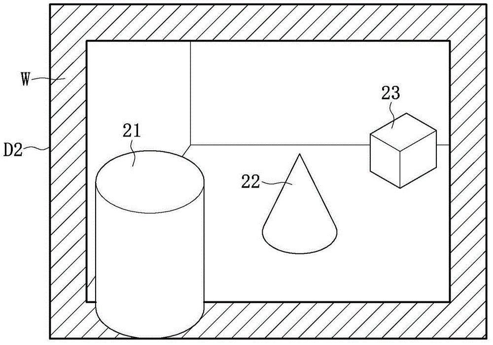
[0042] Please also refer to Figure 1 to Figure 3 , image 3 is the first composite image according to an embodiment of the present invention. Assuming that the user selects the object 21 (which can be regarded as a target object), the processing module 12 will capture the object 21 from the panoramic depth map D1 according to the depth map corresponding to the panoramic depth map D1, and zoom in on the captured object 21. Item 21. Next, the processing module 12 uses the depth-of-view image D1 as a background image to sequentially superimpose the frame image W and the enlarged object 21, thereby generating image 3 The composite image D2 shown is used to highlight the object 21 to achieve a three-dimensional effect.

Embodiment 2

[0044] Please also refer to figure 1 , figure 2 and Figure 4 , Figure 4 is the second composite image according to an embodiment of the present invention. Assuming that the user selects the object 22 (which can be regarded as a target object), the processing module 12 retrieves the object 22 from the full depth map D1 according to the depth map corresponding to the full full depth map D1. In addition, the processing module 12 also captures partial images including the object 22 and the object 23 in the depth-of-view map D1, that is, the processing module 12 captures the image D11 from the depth-of-view map D1 (such as figure 2 shown). Next, the processing module 12 zooms in on the captured object 22, and uses the image D11 as a background image to sequentially superimpose the frame image W and the enlarged object 22, thereby generating the following: Figure 4 The composite image D3 shown is used to highlight the object 22 to achieve a three-dimensional effect.

[00...

Embodiment 3

[0047] In this embodiment, the user can select a reference depth value through the icons displayed on the display module 11 . Please refer again Figure 1 to Figure 3 , assuming that the depth values ​​of object 21, object 22, and object 23 are 20, 100, and 200 respectively, and assuming that the reference depth value selected by the user is 50, the processing module 12 will combine the reference depth value with object 21, object 22, and object 23 to determine that the depth value of the object 21 is smaller than the reference depth value. Next, the processing module 12 extracts an object 21 (which can be regarded as a target object) whose depth value is smaller than the reference depth value from the panoramic depth map D1 according to the depth map corresponding to the panoramic depth map D1, and enlarges the captured object 21 . Next, the processing module 12 uses the depth-of-view image D1 as a background image to sequentially superimpose the frame image W and the enlar...


PUM


Abstract

The invention provides an image processing method and an electronic device. The image processing method comprises following steps of deciding depth values of multiple objects in original images according to depth images corresponding to the original images, wherein the multiple objects comprise at least one first object and at least one second object, the depth value of the at least one first object is less than that of the at least one second object; obtaining a reference depth value; obtaining at least one first object and a background image according to the original images; keeping the size of the at least one first object or amplifying the at least one first object, wherein the depth value of the at least one first object is less than or equal to the reference depth value; and generating an outline image; and respectively superimposing the at least one first object and the background image before and after the outline image, thus highlighting a target object and realizing a three-dimensional effect.

Description

technical field [0001] The present invention relates to an image processing method and its electronic device, in particular to an image processing method capable of highlighting a target object in front of a frame image to achieve a three-dimensional effect and its electronic device. Background technique [0002] Generally speaking, in order to display the effect of three-dimensional (3D) images, it is usually necessary to provide two different images to the human eyes, so that the human eyes can see different images at the same time and produce parallax, thereby resulting in stereoscopic vision. , for example, a stereoscopic display splits the same image through a grating, so that the image received by both eyes has an offset on the horizontal axis, causing parallax, or people can wear special glasses (such as red and blue (green) glasses). Allowing two eyes to receive images of different colors causes parallax. In this way, due to the parallax between the two images seen ...

Claims


Application Information

Patent Timeline
Patent Type & Authority Applications(China)
IPC IPC(8): H04N13/00H04N13/04
CPCG06T11/60
Inventor 郑青峰
Owner LITE ON ELECTRONICS (GUANGZHOU) LTD
Why Eureka
Try Eureka