Automatic throwing adjusting device

An automatic adjustment and throwing machine technology, applied in the field of agricultural machinery, can solve the problems of difficult material receiving, small throwing force, difficult material receiving, etc., and achieve the effect of ensuring normal receiving, high operating efficiency and reliable performance

Active Publication Date: 2016-07-27
河南金农发科技产业有限公司
View PDF8 Cites 2 Cited by
  • Summary
  • Abstract
  • Description
  • Claims
  • Application Information

AI Technical Summary

Problems solved by technology

[0002] The arc plate of the existing throwing machine is fixedly connected to the throwing casing by bolts, and the distance between the arc plate and the throwing blade is fixed. When the feeding amount is different, the length of the material throwing distance is different, which makes it difficult to accept the material
This is because the distance between the arc plate and the throwing blade is designed according to the large feeding amount. When the feeding amount of the throwing machine is large, the throwing distance of the material meets the requirements, and the material can be received normally, but the throwing machine is small. In the case of feeding amount, the throwing force of the material under the same throwing distance will be smaller, resulting in a shorter throwing distance and difficulty in receiving the material

Method used


Image

  • Automatic throwing adjusting device
  • Automatic throwing adjusting device
  • Automatic throwing adjusting device

Examples


Embodiment Construction

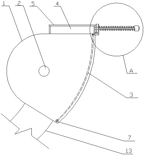
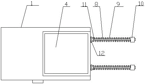
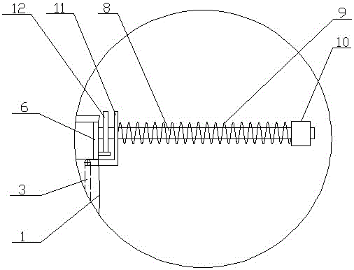
[0020] Such as Figure 1 to Figure 3 As shown, a throwing automatic adjustment device of the present invention includes a throwing casing 1 and a throwing rotating shaft 2 pierced on the throwing casing, and the top of the throwing casing 1 is provided with a throwing outlet 4, An outlet frame 5 is arranged around the throwing outlet 4, a throwing blade is arranged on the throwing rotating shaft 2, and a throwing arc plate installation position is arranged at the throwing direction of the throwing blade, and the outlet frame 5 is close to the throwing arc plate The frame of the installation position is called the installation frame 6, and the elastic throwing arc plate 3 is arranged at the installation position of the throwing arc plate. It is connected with the installation frame 6 through an elastic connection structure, the lower side of the throwing arc plate 3 is connected with the throwing casing 1 through a rotating connection structure, and the left side and the right ...


PUM


Abstract

The invention discloses an automatic throwing adjusting device which comprises a throwing machine shell and a throwing rotating shaft. The top of the throwing machine shell is provided with a throwing outlet. An outlet frame is arranged around the throwing outlet. The throwing rotating shaft is provided with a throwing blade. A throwing arc plate installation station is arranged in the throwing direction of the throwing blade. The frame, close to the throwing arc plate installation station, of the outlet frame is called as an installation frame. A throwing arc plate is arranged at the position of the throwing arc plate installation station. The upper side edge of the throwing arc plate is connected with the installation frame through an elastic connection structure. The lower side edge of the throwing arc plate is connected with the throwing machine shell through a rotary connection structure. The left side edge and the right side edge of the throwing arc plate are in sliding connection with the inner wall of the throwing machine shell. The automatic throwing adjusting device is simple in structure, reliable in performance, high in operation efficiency and capable of automatically adjusting throwing force, can meet the requirement for throwing distance of materials under the condition of large feed quantity and small feed quantity, and ensures that materials are normally received.

Description

technical field [0001] The invention belongs to the technical field of agricultural machinery, and in particular relates to an automatic adjustment device for throwing. Background technique [0002] The arc plate of the existing throwing machine is fixedly connected to the throwing casing by bolts, and the distance between the arc plate and the throwing blade is fixed. When the feeding amount is different, the length of the material throwing distance is different, which makes it difficult to accept the material . This is because the distance between the arc plate and the throwing blade is designed according to the large feeding amount. When the feeding amount of the throwing machine is large, the throwing distance of the material meets the requirements, and the material can be received normally, but the throwing machine is small. In the case of feeding amount, the throwing force of the material under the same throwing distance will be smaller, resulting in a shorter throwin...

Claims


Application Information

Patent Timeline
Patent Type & Authority Applications(China)
IPC IPC(8): A01D61/00
CPCA01D61/00
Inventor 魏宪波苏晓晴
Owner 河南金农发科技产业有限公司
Why Eureka
Try Eureka