Underbody structure of the vehicle

A vehicle and vehicle body technology, applied in the substructure, vehicle parts, superstructure, etc., can solve the problems of no countermeasures and no attention to the further improvement of small area offset collision safety performance, so as to improve the load transfer performance Effect

Inactive Publication Date: 2018-04-03
MAZDA MOTOR CORP
View PDF8 Cites 0 Cited by
  • Summary
  • Abstract
  • Description
  • Claims
  • Application Information

AI Technical Summary

Problems solved by technology

[0004] However, in Patent Documents 1 and 2, not only did no specific countermeasures be mentioned for small-area offset collisions, but no attention was paid to the further improvement of the safety performance of small-area offset collisions.

Method used


Image

  • Underbody structure of the vehicle
  • Underbody structure of the vehicle
  • Underbody structure of the vehicle

Examples


Embodiment Construction

[0043] An embodiment of the present invention will be described in detail below based on the drawings.

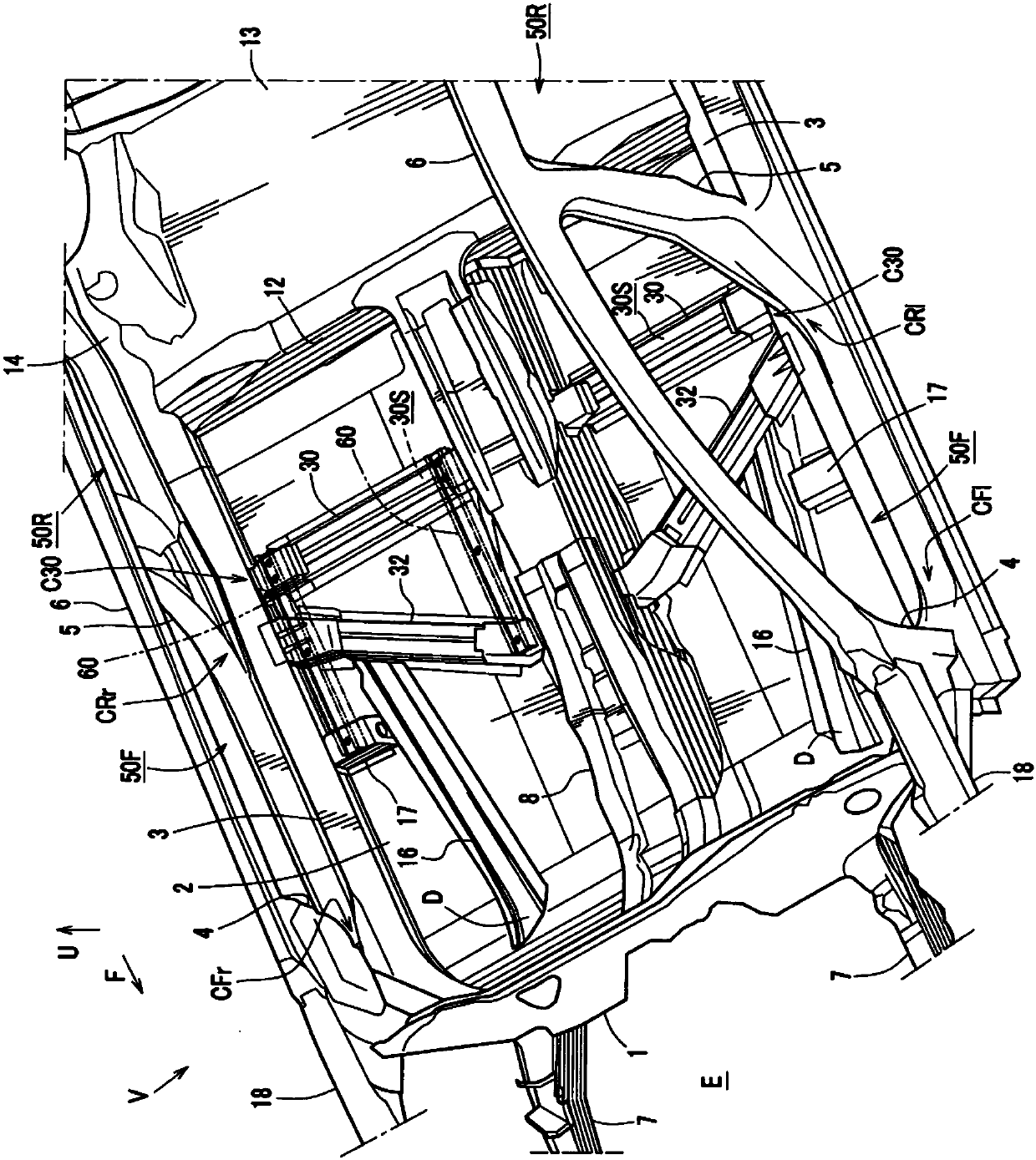
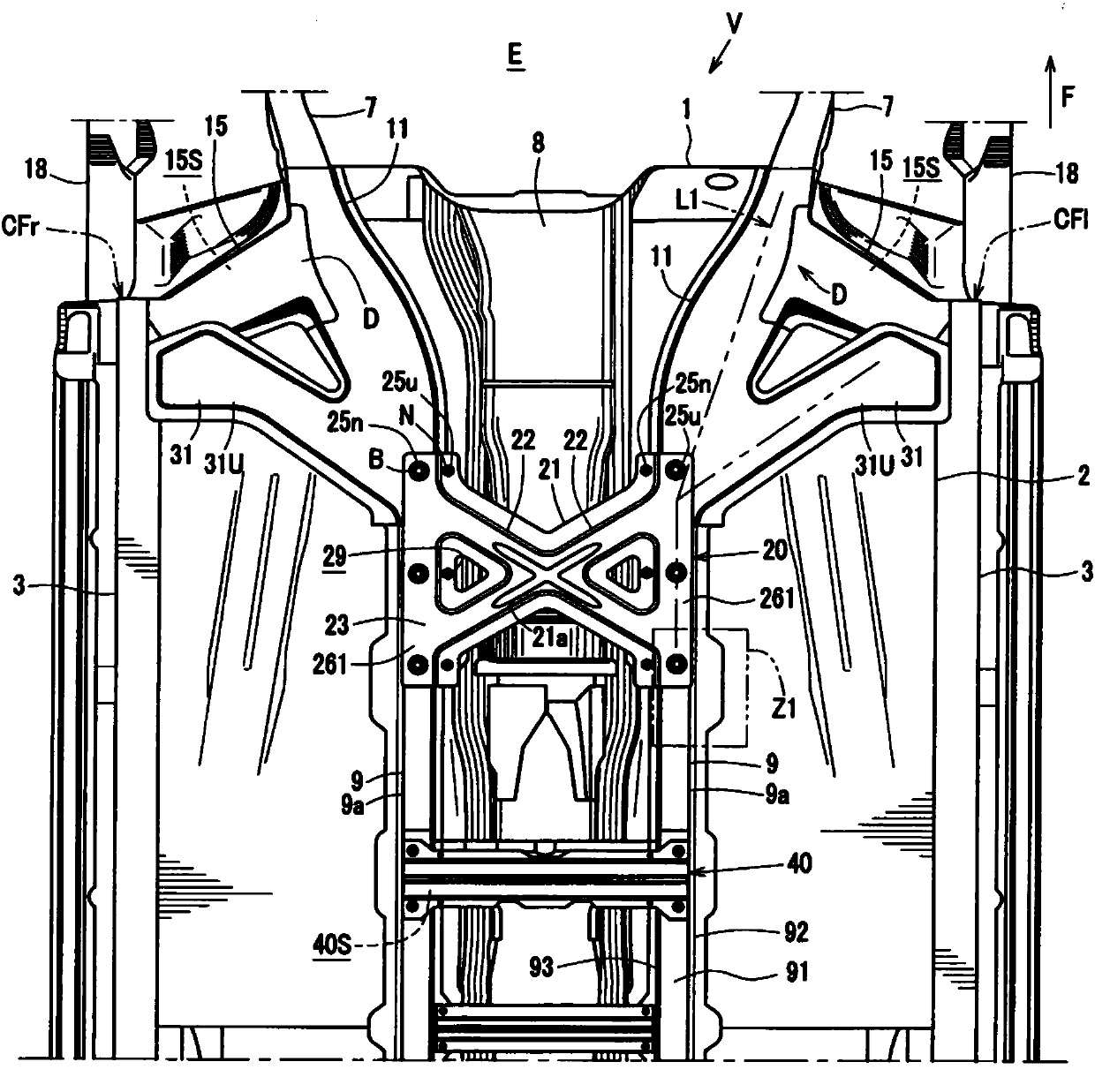
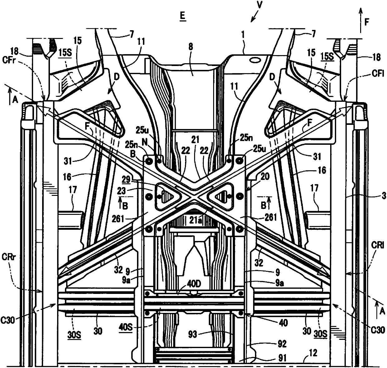
[0044] In addition, in the drawings, an arrow (F) indicates the front of the vehicle body, an arrow (U) indicates the upper side of the vehicle body, an arrow (IN) indicates the inner side of the vehicle body, and an arrow (OUT) indicates the outer side of the vehicle body.

[0045] The drawings show the lower body structure of the vehicle V of this embodiment,figure 1 shows a perspective view viewed from the plane of the lower body structure of the vehicle, figure 2 A bottom view showing the structure of the lower body of the vehicle, image 3 A bottom view showing the structure of the lower body of the vehicle, Figure 4 is to make image 3 The cross-sectional view of the A-A line in the vertical direction is reversed, Figure 5 It is a cross-sectional view of a predetermined portion in the vertical direction of the lower body structure of the present vehicle cut with...


PUM


Abstract

During an SOL collision or a side collision, the load transmission efficiency between the front end of the side sill and the side sill disposed on the opposite side in the vehicle width direction relative to the side sill is improved. A pair of left and right inclined beams (20, 31, 32) are disposed on the upper or lower portion of the floor (2). A pair of slanted beams (20, 31, 32) connect the front part of the side beam (3) extending in the vehicle front-rear direction on the outside of the vehicle body in the vehicle width direction and the hinge pillar (4) extending upward from the front position. ) near the joint site CFr, CF1, and the side beam (3) on the opposite side of the joint site in the vehicle width direction and the center pillar (5) extending upward from the middle position of the side beam (3) in the front and rear direction of the vehicle body CR1 and CRr are connected near the binding site.

Description

technical field [0001] The present invention relates to an underbody structure of a vehicle. The underbody structure of a vehicle includes: left and right side sills extending along the vehicle front-rear direction outside the vehicle body in the vehicle width direction; The central pillar extends upward from the respective middle positions of the left and right side beams in the front-rear direction of the vehicle body; the floor connects the left and right side beams; and the floor tunnel bulges upward at the center of the floor. Background technique [0002] As the lower body structure of a conventional vehicle, in order to ensure the safety performance of the offset collision, for example, the lower body structure of the vehicle of Patent Document 1 and 2 is proposed, and in order to ensure the safety performance of the side collision, for example, the vehicle of the Patent Document 1 is proposed. Underbody construction. [0003] However, in recent years, not only the f...

Claims


Application Information

Patent Timeline
Patent Type & Authority Patents(China)
IPC IPC(8): B62D21/00
CPCB62D25/2036B62D25/20
Inventor 枣裕贵丸山贤司后藤英贵木崎勇中村悟志桥田光二
Owner MAZDA MOTOR CORP
Why Eureka
Try Eureka