

Large mining height gob-side entry retaining roadside filling structure and filling body construction method
A technology of large mining height and filling body, which is used in filling materials, mining equipment, earth-moving drilling and mining, etc., can solve the problems of weak resistance to deformation, excessive wood consumption, and excessive deformation, so as to improve the resistance to buckling deformation. Increase the bonding area and facilitate installation
- Summary
- Abstract
- Description
- Claims
- Application Information
AI Technical Summary
Problems solved by technology
Method used
Image

Examples
Embodiment Construction
[0037] The present invention will be further described below in conjunction with accompanying drawing.
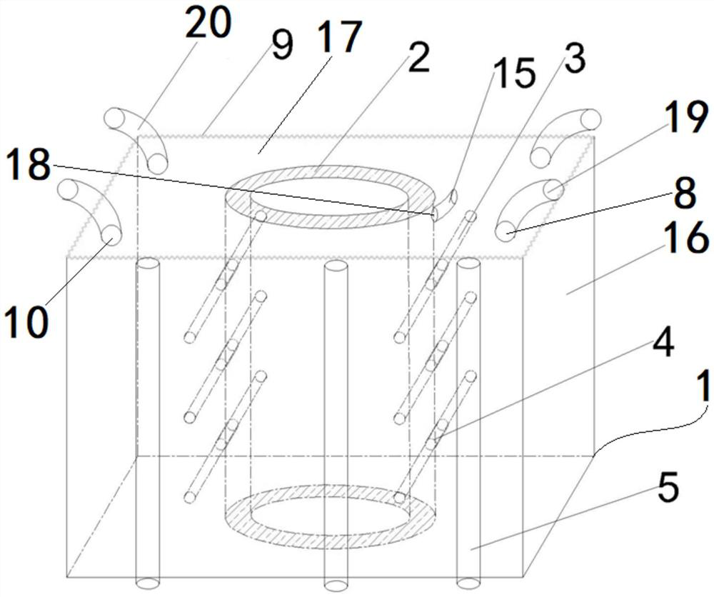
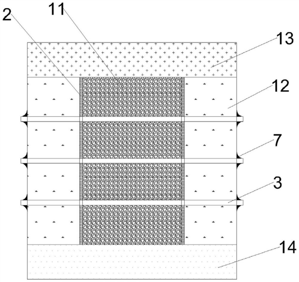
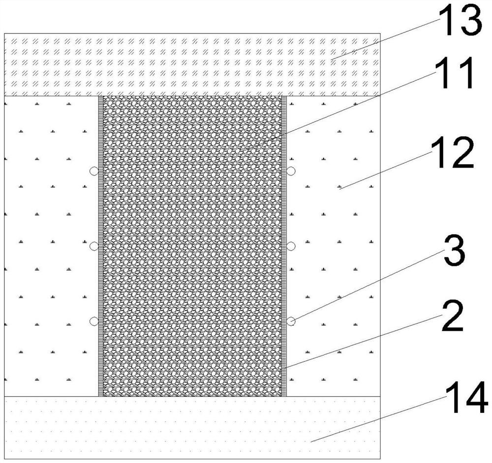
[0038] Such as Figure 1 to Figure 4 As shown, a large mining height gobside filling structure includes a single hydraulic prop 5, a steel mesh 6 and a filling bag 1;
[0039] A plurality of single hydraulic props 5 are divided into two rows, and are respectively vertically supported on the outer sides of the two ends of the width direction of the area to be filled;
[0040] Multiple pieces of steel mesh 6 are sequentially arranged around the area to be filled, and hung on the inner side of the single hydraulic prop 5, and a three-dimensional filling space for the wall to be filled is formed above the area to be filled;
[0041] The filling bag 1 is a three-dimensional structure with a closed space, and its height is the same as the distance between the bottom plate 14 and the top plate 13 of the area to be filled; The side walls around it are connected to the steel mesh ...
PUM
 Abstract
Description
Claims
Application Information